
Display device

a technology of display device and light guide plate, which is applied in the direction of optical light guide, instruments, optics, etc., can solve the problems of increased viewing angle difference, ineffective alignment of light guide plate with light source, and increased viewer's look at the left and right end portions of the screen, so as to improve light incidence efficiency

Inactive Publication Date: 2018-09-13
SAMSUNG DISPLAY CO LTD
View PDF2 Cites 1 Cited by
  • Summary
  • Abstract
  • Description
  • Claims
  • Application Information

AI Technical Summary

Benefits of technology

The patent text discusses the problem of a curved display device having a decreased luminance due to a lowered light incidence efficiency caused by a curved light guide plate that does not align effectively with light sources. The technical effect is an improvement in the light incidence efficiency of a curved display device through the use of a curved light guide plate.

Problems solved by technology

However, as the screen size of the LCD device increases, a viewing angle difference between a case in which a viewer looks at a center portion of a screen and a case in which the viewer looks at left and right end portions of the screen increases.
As the light guide plate is curved, a side surface of the light guide plate in the longitudinal direction is inclined and the light guide plate may not be effectively aligned with light sources.

Method used


Image

  • Display device
  • Display device
  • Display device

Examples


Embodiment Construction

[0026]The invention now will be described more fully hereinafter with reference to the accompanying drawings, in which various embodiments are shown. This invention may, however, be embodied in many different forms, and should not be construed as limited to the embodiments set forth herein. Rather, these embodiments are provided so that this disclosure will be thorough and complete, and will fully convey the scope of the invention to those skilled in the art. Like reference numerals refer to like elements throughout.

[0027]In the drawings, thicknesses of a plurality of layers and areas are illustrated in an enlarged manner for clarity and ease of description thereof. When a layer, area, or plate is referred to as being “on” another layer, area, or plate, it may be directly on the other layer, area, or plate, or intervening layers, areas, or plates may be therebetween. Conversely, when a layer, area, or plate is referred to as being “directly on” another layer, area, or plate, interve...


PUM


Abstract

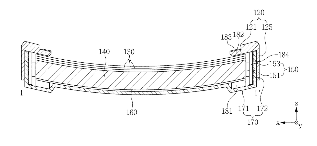
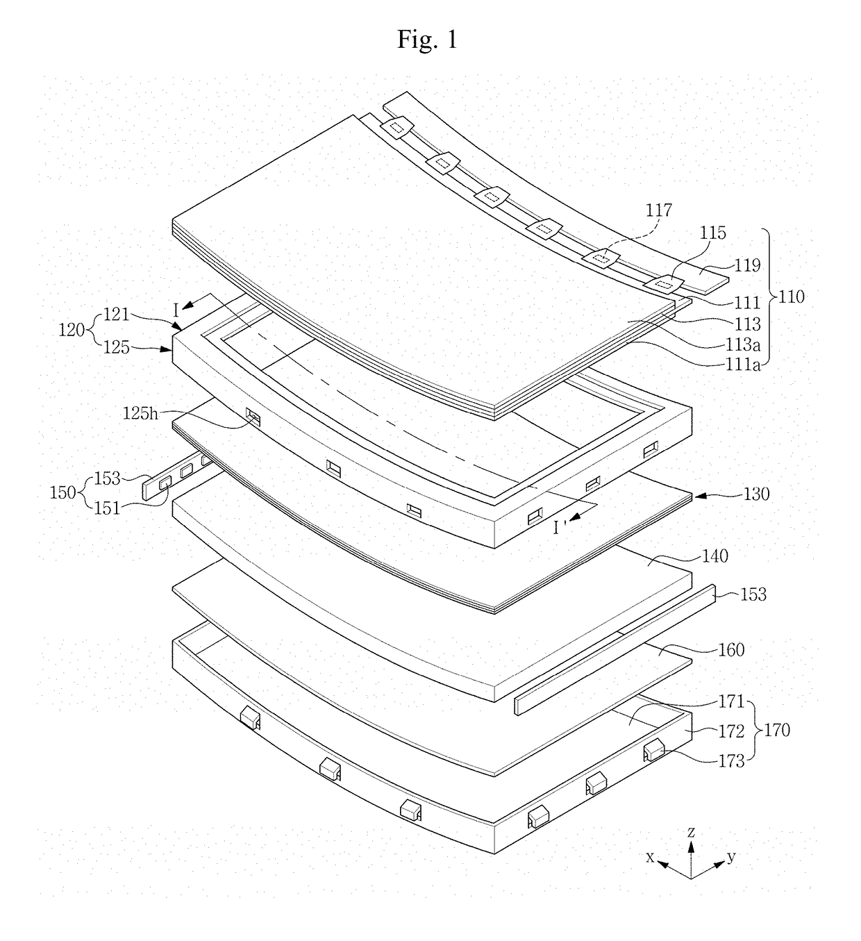
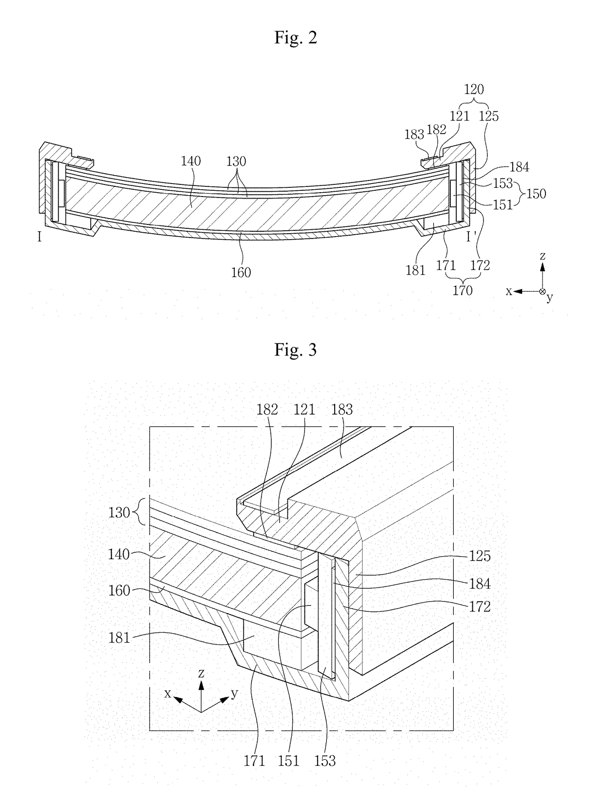
A display device includes: a display panel curved in a first direction; a light source which emits a light; and a light guide plate which guides the light from the light source toward the display panel. The light guide plate includes an exit surface curved in the first direction corresponding to a shape of the display panel and an incidence surface, which is defined by a side surface of the light guide plate in the first direction, where the light from the light source is incident onto the incidence surface. The incidence surface is substantially parallel to a normal line at a central portion of the exit surface.

Description

CROSS-REFERENCE TO RELATED APPLICATION[0001]This application is a continuation-in-part of U.S. patent application Ser. No. 15 / 196,204, filed on Jun. 29, 2016, which claims priority to Korean Patent Application No. 10-2015-0154074, filed on Nov. 3, 2015. This application claims priority to Korean Patent Application No. 10-2017-0155505, filed on Nov. 21, 2017, and all the benefits accruing therefrom under 35 U.S.C. §§ 119, the contents of which in their entirety are herein incorporated by reference.BACKGROUND1. Field[0002]Exemplary embodiments of the invention relate to a display device, and more particularly, to a display device including a light guide plate with increased light incidence efficiency.2. Discussion of Related Art[0003]In general, a flat panel display (“FPD”) device, such as a liquid crystal display (“LCD”) device or an organic light emitting diode (“OLED”) display device, typically includes a plurality electric-field generating electrodes and an electro-optical active ...

Claims


Application Information

Patent Timeline
IPC IPC(8): F21V8/00G02F1/1335G02F1/1333G02F1/1345
CPCG02B6/0073G02B6/0055G02B6/0088G02F1/133514G02F1/133305G02F1/133308G02F1/13452G02F2201/121G02F2201/123G02B6/0083G02B6/0091
Inventor BAEK, MYUNGHUNKIM, TAECHANGLEE, DONGCHEOLSHIN, TAEKSUNKIM, DOHUNKIM, MANSOOKIM, HYUNHYANGPARK, YOUNGMINSON, JUNHEELEE, WONCHULJUNG, YOUNGGYU
Owner SAMSUNG DISPLAY CO LTD
Learn More