Security elements and methods of manufacture thereof

a technology of security elements and manufacturing methods, applied in the field of security elements, can solve the problems of loss of clarity or definition of verifiable optically variable effects, sensitive illumination conditions of clarity etc., and achieve the effect of improving the appearance of optically variable effects and enhancing diffractive efficiency

Active Publication Date: 2021-02-25
DE LA RUE INT LTD
View PDF10 Cites 0 Cited by
  • Summary
  • Abstract
  • Description
  • Claims
  • Application Information

AI Technical Summary

Benefits of technology

[0006]The security element of the present invention provides first and second diffractive optically variable effect generating structures, typically structures that are different from one another (e.g. arranged in different patterns), across arrays of corresponding first and second sub-regions with respective inclinations. By providing diffractive optically variable effect generating structures at different inclinations, the angle of incidence of light is effectively altered between the first and second sub-regions. This allows for improved control over the diffractive replay of the structures included in the security element at the respective different inclinations. For example, the increase in the number of effective angles of incidence can provide an alternative to varying other parameters, such as orientation, for providing optical variability in a second direction, can increase the number of viable viewing angles which satisfy the replay criteria for zero order and other nano-grating structures and can improve the clarity of devices viewed in diffuse lighting conditions. More detailed examples of these effects will be discussed below.
[0054]Preferably, the method further comprises depositing an opaque reflector layer onto the first surface in at least the first and second sub-regions. An opaque reflector layer enhances diffractive efficiency, improving the appearance of the optically variable effects.

Problems solved by technology

A problem with security elements that utilise first order diffraction gratings with spatial periods of 0.7 micrometres or more is that the clarity of the optically variable effect is sensitive to illumination conditions.
However under diffuse, extended or multiple light sources multiple or substantial parts of the animation or 3D parallax effect are visualised simultaneously to the extent that the verifiable optically variable effect loses clarity or definition.

Method used


Image

  • Security elements and methods of manufacture thereof
  • Security elements and methods of manufacture thereof
  • Security elements and methods of manufacture thereof

Examples


Embodiment Construction

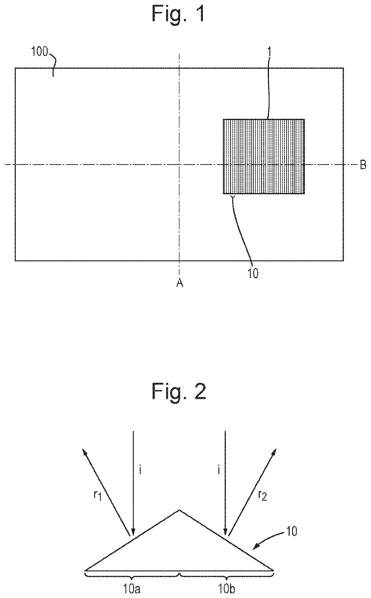
[0083]A security element according to a first embodiment will now be described with reference to FIGS. 1 to 4B.

[0084]FIG. 1 shows a security document 100, in this case a banknote, with a security element 1. The security document has a short axis A and a long axis B perpendicular to the short axis. The security document is observed during normal viewing with the short axis A being substantially vertical and the long axis B being substantially horizontal. The security element has a first surface that faces away from the security document. This first surface is made up of an array of image regions 10, in this case elongate image regions, each elongate image region extending in a first direction, i.e. along the direction of the axis A. The array of elongate image regions are arranged so as to repeat along a second direction along the surface, i.e. along the direction of axis B, the image regions repeating so as to provide the width of the security element.

[0085]FIG. 2 shows the arrangem...


PUM


Abstract

A security element including: a first layer having a first surface; an array of image regions across the surface, each region including at least first and second sub-regions; a first diffractive optically variable effect generating structure in or on the surface across the first sub-regions; and a second diffractive optically variable effect generating structure in or on the surface across the second sub-regions; wherein the surface is arranged so each first sub-region has a first average inclination and each second sub-region has a second average inclination different from the first, wherein the first structure and inclination provide that the first effect is exhibited across the first sub-regions at least at a first viewing angle and the second structure and inclination provide that the second effect is exhibited across the second sub-regions at least at a second viewing angle different from the first. Also, a method of manufacturing the security element.

Description

FIELD OF THE INVENTION[0001]The present invention relates to security elements such as those suitable for use in or on security documents such as banknotes, identity documents, passports, certificates and the like, as well as methods for manufacturing such security elements.DESCRIPTION OF THE RELATED ART[0002]To prevent counterfeiting and enable authenticity to be checked, security documents are typically provided with one or more security elements which are difficult or impossible to replicate accurately with commonly available means, particularly photocopiers, scanners or commercial printers.[0003]Many conventional security elements utilise diffractive optically variable effect generating relief structures, such as diffraction gratings, to provide an optically variable effect, i.e. an appearance that changes upon tilting or rotation of the device, which cannot be replicated by copying, as with a photocopier or scanner or by printing techniques. A problem with security elements tha...

Claims


Application Information

Patent Timeline
Patent Type & Authority Applications(United States)
IPC IPC(8): B42D25/328B42D25/324G02B5/18
CPCB42D25/328B42D25/324B42D25/373G02B5/1819G02B5/1847B42D25/29B42D25/23B42D25/24B42D25/45G02B5/1857
Inventor HOLMES, BRIAN
Owner DE LA RUE INT LTD
Why Eureka
Try Eureka