Planar Light Source and Method for Producing Light-Emitting Device

a light source and light guide plate technology, applied in the field of planar light sources, can solve the problem of insufficient light output of light-emitting devices inside the light guide plate, and achieve the effect of improving light output and efficient inciden

Active Publication Date: 2015-06-18
TOYODA GOSEI CO LTD
View PDF2 Cites 0 Cited by
  • Summary
  • Abstract
  • Description
  • Claims
  • Application Information

AI Technical Summary

Benefits of technology

[0013]The processes are preferably as follows. In the forming only long side grooves, the grooves are formed by laser processing, and a modified portion is formed in an area of the semiconductor layer which area is near the substrate. In the wet etching, the lateral surfaces of the semiconductor layer are reversed tapered with the modified portion as a starting point of wet etching. Thus, the lateral surfaces of the sem...

Problems solved by technology

However, in the conventional planar light source combining the light guide plate and the light-emitting app...

Method used


Image

  • Planar Light Source and Method for Producing Light-Emitting Device
  • Planar Light Source and Method for Producing Light-Emitting Device
  • Planar Light Source and Method for Producing Light-Emitting Device

Examples


embodiment 1

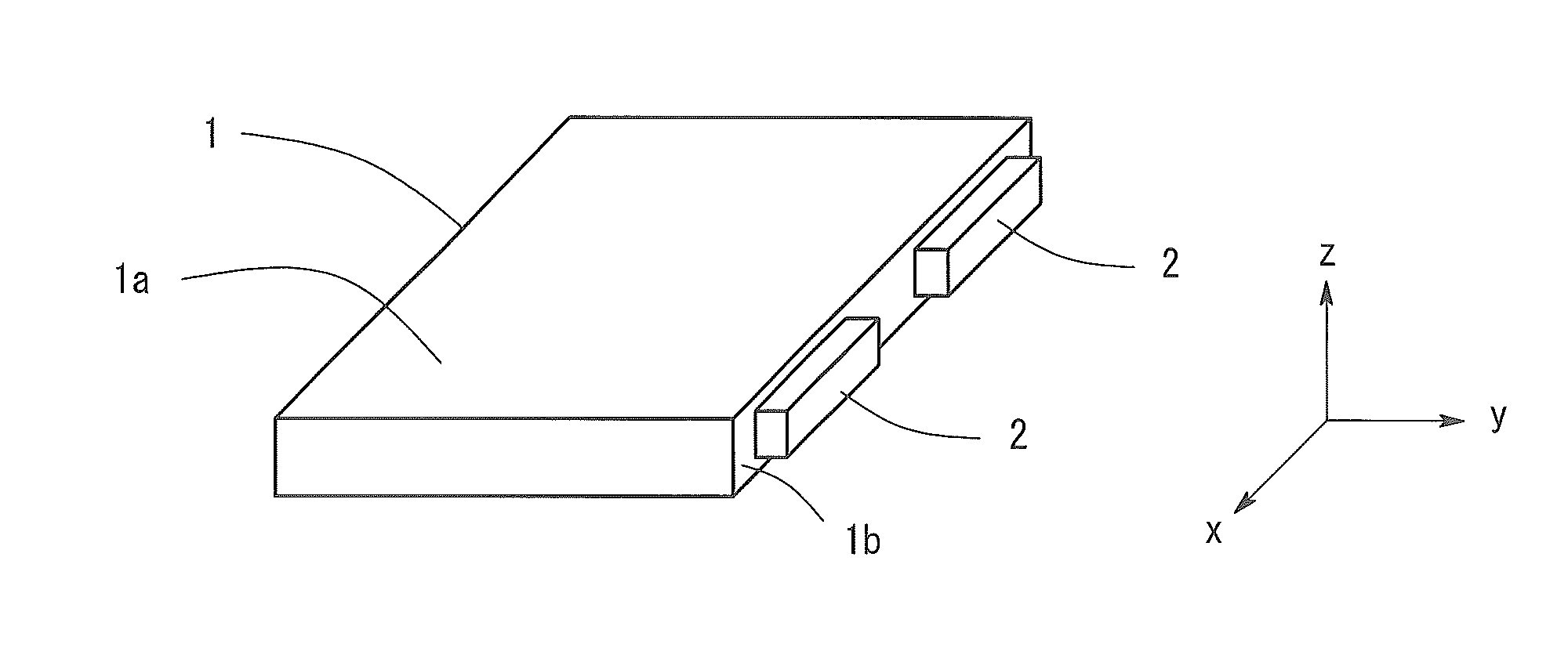
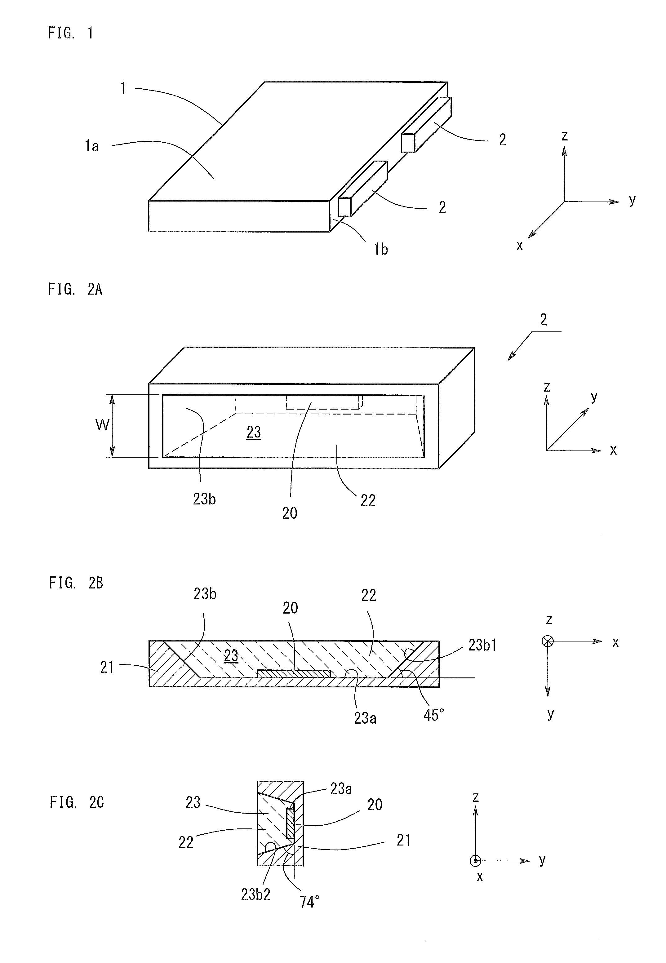
[0027]FIG. 1 shows the structure of a planar light source according to Embodiment 1. As shown in FIG. 1, a planar light source according to Embodiment 1 comprises a light guide plate 1 and a light-emitting apparatus 2.

[0028]The light guide plate 1 has a rectangular planar shape made of resin transparent to visible light, such as acrylic resin, polycarbonate resin, and cycloolefin polymer resin.

[0029]A plurality of light-emitting apparatuses 2 is disposed along a lateral surface 1b of the light guide plate 1. The light-emitting apparatus 2 is a light source which has a long rectangular shape and emits white light. The light-emitting apparatus 2 is disposed so as to emit light toward the lateral surface of the light guide plate 1. A light from the light-emitting apparatus 2 is incident in the light guide plate 1, the light is multi-reflected inside the light guide plate 1, and extracted from an entire top surface 1a of the light guide plate 1 while being guided toward the opposite lat...


PUM


Abstract

A planar light source comprises a light guide plate and a light-emitting apparatus disposed on a lateral surface of the light guide plate. The light-emitting apparatus comprises a light-emitting device, a case, and a sealing resin. The light-emitting device has a rectangular shape in a plan view, a long-side lateral surface of a semiconductor layer is reversed tapered having an inclination such that a cross section area increases in a direction parallel to a main surface of a sapphire substrate as a distance from the sapphire substrate increases, and a short-side lateral surface is perpendicular to the main surface of the sapphire substrate. A short-side and a long-side direction of the light-emitting device are perpendicular and parallel to the planar main surface of the light guide plate, respectively. The main surface of the light-emitting device is parallel to the lateral surface of the light guide plate.

Description

BACKGROUND OF THE INVENTION[0001]1. Field of the Invention[0002]The present invention relates to a planar light source combining a light guide plate and a light-emitting apparatus, wherein a light coming from the light-emitting apparatus is introduced into the light guide plate through a lateral surface of the light guide plate and is emitted from a top surface of the light guide plate. More particularly, the present invention resides in a light-emitting apparatus employing a Group III nitride semiconductor light-emitting device. The present invention also relates to a method for producing a Group III nitride semiconductor light-emitting device.[0003]2. Background Art[0004]A planar light source combining a light guide plate and a light-emitting apparatus has been widely known, for example, from Japanese Patent Application Laid-Open (kokai) No. 2008-108994. In such a light source, the light-emitting apparatus is disposed on a lateral surface of the light guide plate made of transpare...

Claims


Application Information

Patent Timeline
IPC IPC(8): F21V8/00H01L33/54H01L33/20H01L33/50H01L33/00H01L33/32
CPCG02B6/0073H01L33/0066H01L33/0075H01L33/54H01L33/20H01L33/507H01L33/32G02B6/0031H01L33/0062H01L33/48H01L33/50
Inventor TOTANI, SHINGO
Owner TOYODA GOSEI CO LTD
Why Eureka
Try Eureka