
Planar light source and method for producing light-emitting device

a light source and light guide plate technology, applied in the field of planar light sources, can solve the problem of insufficient light output of light-emitting devices inside the light guide plate, and achieve the effect of improving light output and efficient inciden

Active Publication Date: 2018-10-16
TOYODA GOSEI CO LTD
View PDF16 Cites 0 Cited by
  • Summary
  • Abstract
  • Description
  • Claims
  • Application Information

AI Technical Summary

Benefits of technology

The present invention provides a planar light source with improved light output that is suitable for use with a light-emitting device. The light guide plate has a long-side lateral surface that is inclined by 5° to 85° to the substrate surface, which redirects and focuses light emitted from the device, resulting in more efficient light coupling with the guide plate. The light guide plate has a thickness of one to ten times the width in the short-side direction of the opening of the concave portion of the case, which allows for a smaller size of the light source. The method for producing the light-emitting device includes forming long side grooves by laser processing and wet etching using the modified portion of the semiconductor layer as a starting point. Overall, the present invention provides a more efficient and controllable light source for various applications.

Problems solved by technology

However, in the conventional planar light source combining the light guide plate and the light-emitting apparatus, the rate of light from the light-emitting apparatus taken inside the light guide plate is not sufficient.

Method used


Image

  • Planar light source and method for producing light-emitting device
  • Planar light source and method for producing light-emitting device
  • Planar light source and method for producing light-emitting device

Examples


embodiment 1

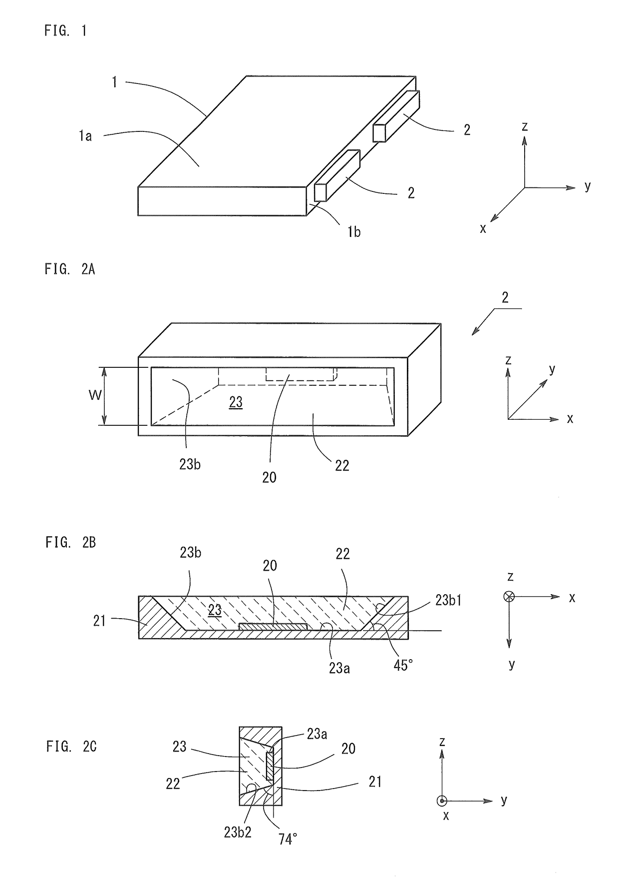
[0027]FIG. 1 shows the structure of a planar light source according to Embodiment 1. As shown in FIG. 1, a planar light source according to Embodiment 1 comprises a light guide plate 1 and a light-emitting apparatus 2.

[0028]The light guide plate 1 has a rectangular planar shape made of resin transparent to visible light, such as acrylic resin, polycarbonate resin, and cycloolefin polymer resin.

[0029]A plurality of light-emitting apparatuses 2 is disposed along a lateral surface 1b of the light guide plate 1. The light-emitting apparatus 2 is a light source which has a long rectangular shape and emits white light. The light-emitting apparatus 2 is disposed so as to emit light toward the lateral surface of the light guide plate 1. A light from the light-emitting apparatus 2 is incident in the light guide plate 1, the light is multi-reflected inside the light guide plate 1, and extracted from an entire top surface 1a of the light guide plate 1 while being guided toward the opposite lat...


PUM


Abstract

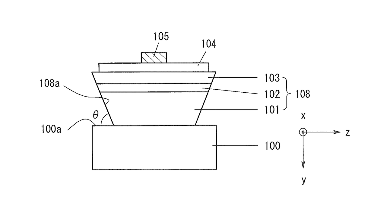
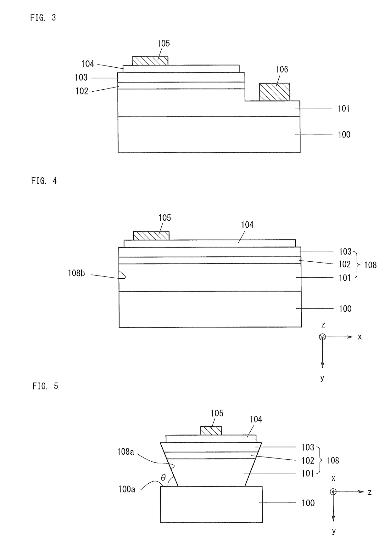
A planar light source comprises a light guide plate and a light-emitting apparatus disposed on a lateral surface of the light guide plate. The light-emitting apparatus comprises a light-emitting device, a case, and a sealing resin. The light-emitting device has a rectangular shape in a plan view, a long-side lateral surface of a semiconductor layer is reversed tapered having an inclination such that a cross section area increases in a direction parallel to a main surface of a sapphire substrate as a distance from the sapphire substrate increases, and a short-side lateral surface is perpendicular to the main surface of the sapphire substrate. A short-side and a long-side direction of the light-emitting device are perpendicular and parallel to the planar main surface of the light guide plate, respectively. The main surface of the light-emitting device is parallel to the lateral surface of the light guide plate.

Description

BACKGROUND OF THE INVENTION[0001]Field of the Invention[0002]The present invention relates to a planar light source combining a light guide plate and a light-emitting apparatus, wherein a light coming from the light-emitting apparatus is introduced into the light guide plate through a lateral surface of the light guide plate and is emitted from a top surface of the light guide plate. More particularly, the present invention resides in a light-emitting apparatus employing a Group III nitride semiconductor light-emitting device. The present invention also relates to a method for producing a Group III nitride semiconductor light-emitting device.[0003]Background Art[0004]A planar light source combining a light guide plate and a light-emitting apparatus has been widely known, for example, from Japanese Patent Application Laid-Open (kokai) No. 2008-108994. In such a light source, the light-emitting apparatus is disposed on a lateral surface of the light guide plate made of transparent res...

Claims


Application Information

Patent Timeline
Patent Type & Authority Patents(United States)
IPC IPC(8): F21V7/04F21V8/00H01L33/20H01L33/00H01L33/50H01L33/48
CPCG02B6/0073H01L33/20H01L33/50H01L33/48H01L33/0062G02B6/0031
Inventor TOTANI, SHINGO
Owner TOYODA GOSEI CO LTD
Learn More