Connector Integration for Smart Clothing

a technology of connecting threads and smart clothing, applied in contact forms, instruments, weaving, etc., can solve the problems of difficulty for manufacturers to attach individual conductive threads to electronic components, and achieve the effect of improving the integration efficiency of the connection field

Active Publication Date: 2018-09-13
GOOGLE LLC
View PDF0 Cites 21 Cited by
  • Summary
  • Abstract
  • Description
  • Claims
  • Application Information

AI Technical Summary

Benefits of technology

This patent describes how conductive threads are used in interactive objects like clothing or jewelry. These threads have two ends - one attached to an electronic device and another that's part of the object itself. To prevent damage during use, there's some extra space (called slack) between these points. This allows for relaxation without compromising the connection between the electronics and the object. The length of this slack depends on the specific design but should always be longer than half its size.

Problems solved by technology

This patent describes an innovative technology called interactive textile which has conductive thread embedded in it to create a touch sensor. This allows users to control different functions through their touch input on the textile. However, there have been difficulties attaching separate conductive threads to other electronic components like batteries and processors.

Method used


Image

  • Connector Integration for Smart Clothing
  • Connector Integration for Smart Clothing
  • Connector Integration for Smart Clothing

Examples


example environment

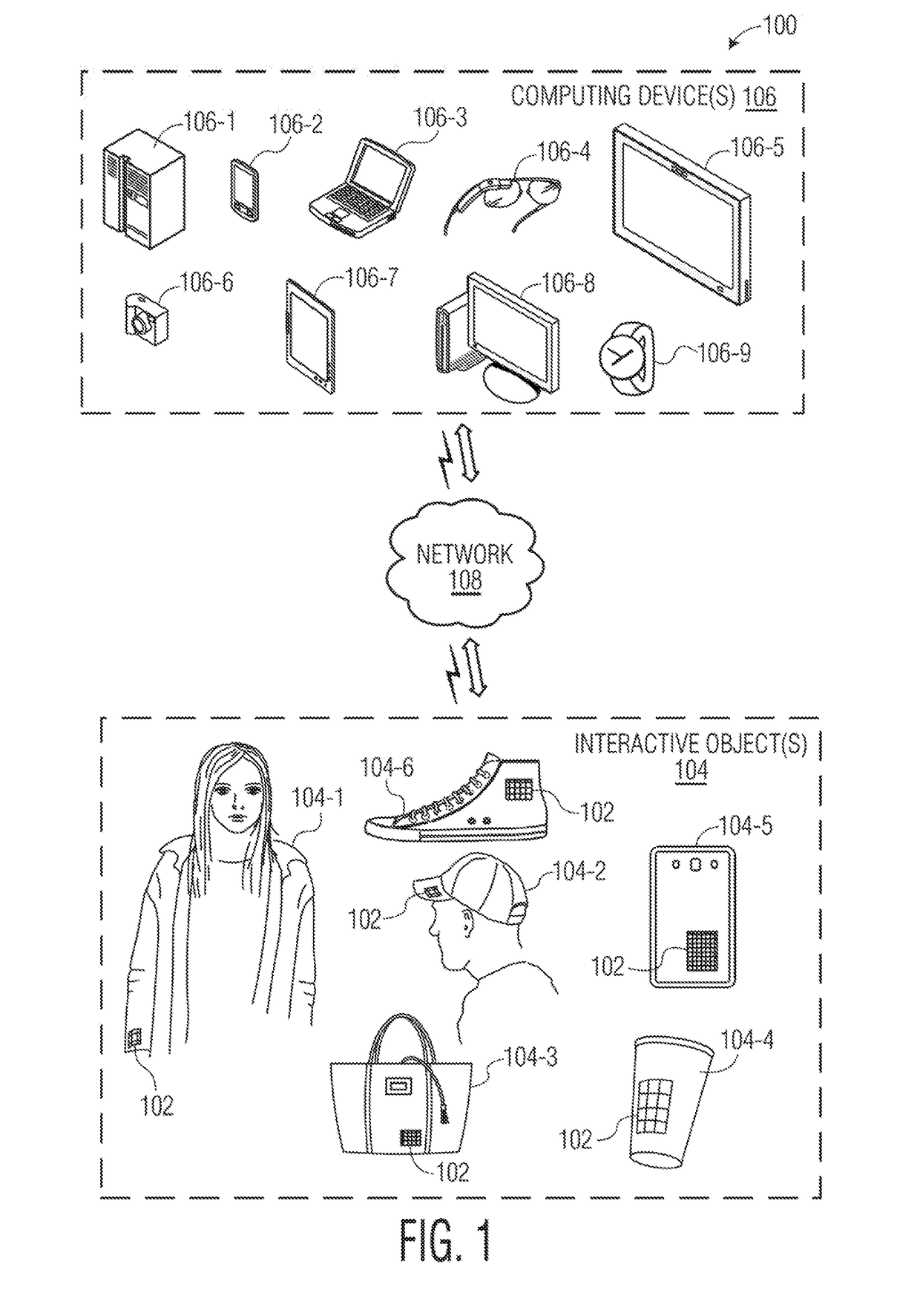
[0038]FIG. 1 is an illustration of an example environment 100 in which an interactive textile with multiple electronics modules can be implemented. Environment 100 includes an interactive textile 102, which is shown as being integrated within various interactive objects 104. Interactive textile 102 is a textile that is configured to sense multi-touch-input. As described herein, a textile corresponds to any type of flexible woven material consisting of a network of natural or artificial fibers, often referred to as thread or yarn. Textiles may be formed by weaving, knitting, crocheting, knotting, pressing threads together or consolidating fibers or filaments together in a nonwoven manner.

[0039]In environment 100, interactive objects 104 include “flexible” objects, such as a shirt 104-1, a hat 104-2, a handbag 104-3 and a shoe 104-6. It is to be noted, however, that interactive textile 102 may be integrated within any type of flexible object made from fabric or a similar flexible mate...


PUM


Abstract

This document describes an interactive object with multiple electronics modules. An interactive object (e.g., a garment) includes a plurality of conductive threads woven into the interactive object, and an internal electronics module coupled to the array of conductive thread. The internal electronics module includes a first subset of electronic components, such as sensing circuitry configured to detect touch-input to the grid of conductive thread. An external electronics module that includes a second subset of electronic components (e.g., a microprocessor, power source, or network interface) is removably coupled to the interactive object via a communication interface. The communication interface enables communication between the internal electronics module and the external electronics module when the external electronics module is coupled to the interactive object.

Description


Claims


Application Information

Patent Timeline
Owner GOOGLE LLC
Why Eureka
Try Eureka