Image Pick-Up Module And Method For Assembling Such An Image Pick-Up Module

a technology of image pick-up modules and assembly methods, which is applied in the field of endoscopes, can solve the problems of increasing assembly effort, affecting the overall structure of the image pick-up modules, and presenting problems such as the bonding of cables and electric components between the boards, and achieves the effect of simple procedur

Inactive Publication Date: 2009-01-29
KARL STORZ GMBH & CO KG
View PDF12 Cites 14 Cited by
  • Summary
  • Abstract
  • Description
  • Claims
  • Application Information

AI Technical Summary

Benefits of technology

[0040]This permits strain relief to be implemented by an especially simple procedure since a curing filling compound can be introduced into the interior of the circuit board in its soft or even flowing condition, without any effort.
[

Problems solved by technology

While presently existing image sensors, designed in so-called “case-less” configuration and with flexible connecting fingers, succeed increasingly in meeting these demands, the problem of making the overall structure of the image pick-up modules as small as possible continues to exist.
Since the signal electronics accommodated on the two circuit boards cannot function independently, an electric connection, for example in the form of lines, or a connecting circuit board must be additionally integrated which constitutes a further increase of the assembly effort connected with the image pick-up module.
In addition, bonding the cables and the electric components between the boards has been found to present a problem.
Another problem presenting itself when such image pick-up modules are used in video endoscopes consists in that the one or the several cables, that lead away from the circuit board, may be exposed to tensile strain, especially in the case of flexible video endoscopes or when a deflection mechanism is provided for moving the image pick-up module, as described in U.

Method used


Image

  • Image Pick-Up Module And Method For Assembling Such An Image Pick-Up Module
  • Image Pick-Up Module And Method For Assembling Such An Image Pick-Up Module
  • Image Pick-Up Module And Method For Assembling Such An Image Pick-Up Module

Examples


Embodiment Construction

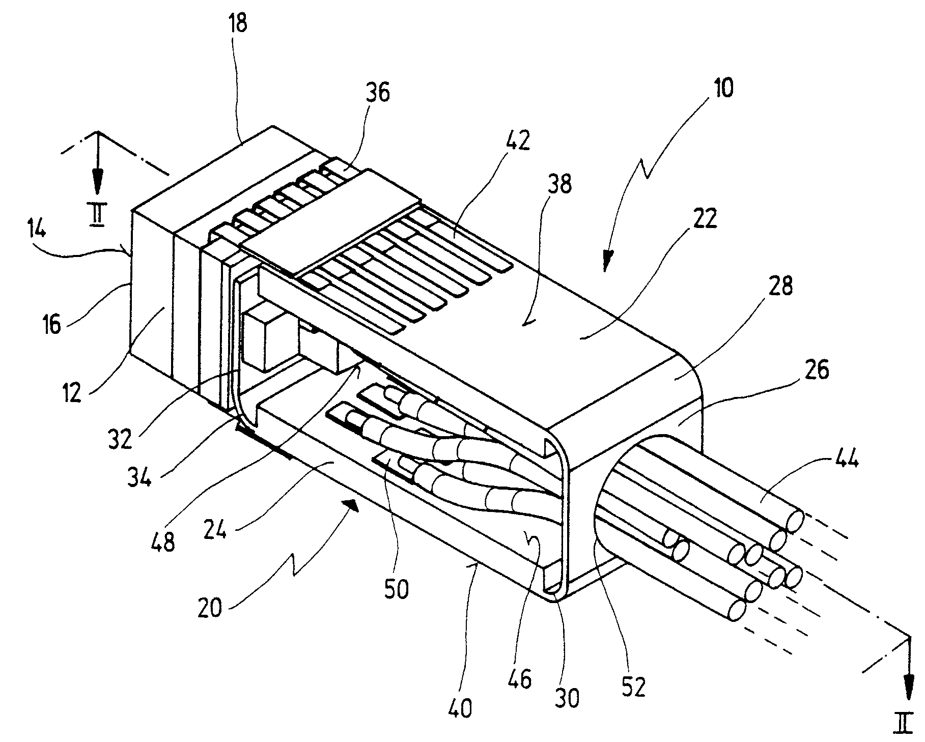
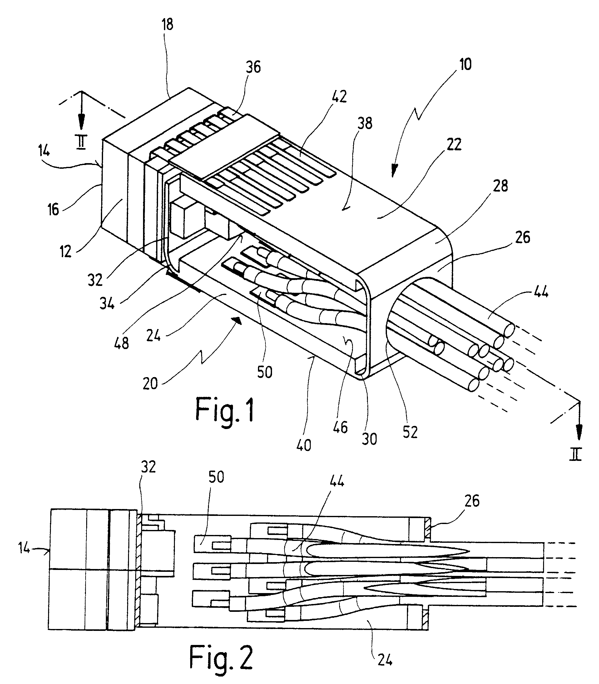
[0074]FIG. 1 shows an electronic image pick-up module, indicated generally by reference numeral 10. The image pick-up module 10 is installed, for example, in the distal tip of an endoscope shaft not shown. As illustrated in FIG. 1, the image pick-up module 10 is ready for being installed, which means that the image pick-up module 10 will not be enclosed in an additional casing; as will be shown in the description that follows, there is no need for such an additional enclosure in the case of that embodiment of the image pick-up module 10 according to the invention since all sensitive and, possibly, strain-loaded elements are safely protected.

[0075]The image pick-up module 10 comprises an image sensor 12 with an image pick-up surface 14.

[0076]The image sensor 12 is an electric image sensor in CCD or CMOS technology. Such image sensors are commercially available. Image sensors of this kind constitute optoelectronic converters, which means that light, which is received via the image pic...


PUM


Abstract

An image pick-up module comprises an electronic image sensor, single-piece circuit board electrically bonded to the image sensor, and at least one cable electrically bonded and leading away from the circuit board. The circuit board has at least three sections, first and second section extending in relation to the other and obliquely or crosswise to the image sensor, and third section arranged between first and second section. The image sensor is arranged on the circuit board opposite the third section. In a method for assembling the image pick-up module, the circuit board has the form of a planar board blank comprising at least three sections folded along flexible connecting sections whereby the at least one cable is bonded to the board, and the board folds whereby a third section is located between first and second section, and the image sensor is bonded to the circuit board opposite the third section.

Description

CROSS-REFERENCE TO RELATED APPLICATIONS[0001]The present application is divisional of pending U.S. patent application Ser. No. 09 / 994,178 filed on Nov. 26, 2001, which is a continuation of International Patent Application PCT / EP2000 / 04792 filed on May 25, 2000, which designates the United States and which claims priority of German patent application 199 24 189 filed on May 27, 1999.FIELD OF THE INVENTION[0002]The present invention relates to an image pick-up module, especially for an endoscope, comprising an electronic image sensor, a single-piece circuit board which is electrically bonded to the image sensor and to which is further electrically bonded at least one cable leading away from the circuit board, the circuit board having at least three sections, with a first section and a second section extending in spaced relation one to the other and obliquely or crosswise to the image sensor and a third section being arranged between the first and the second sections.BACKGROUND OF THE ...

Claims


Application Information

Patent Timeline
IPC IPC(8): H04N9/47A61B1/05H04N5/225
CPCH04N5/2251H04N5/2253A61B1/051A61B1/0011H04N2005/2255H04N23/555H04N23/50H04N23/54
Inventor IRION, KLAUS M.SCHWARZ, PETERKOCHER, MARKKEHR, ULRICH
Owner KARL STORZ GMBH & CO KG
Why Eureka
Try Eureka