Sheet feeder, sheet conveyer having the same, and image forming device having the same

a feeder and conveyer technology, applied in the field of sheet feeders, can solve the problems of high risk of sheet loss or skewing sheet, difficulty in known sheet feeders, and difficulty in feeding multiple sheets, and achieve the effect of increasing demand

Active Publication Date: 2018-09-20
KONICA MINOLTA INC
View PDF8 Cites 3 Cited by
  • Summary
  • Abstract
  • Description
  • Claims
  • Application Information

AI Technical Summary

Benefits of technology

[0007]In recent years, image forming devices such as printers and copiers are widely spread among not only offices of typical sizes but also small offices home offices (SOHO) and standard homes. This increasingly diversifies sheet sizes to be treated by sheet feeders: not only standard sizes specified by Japanese industrial standards (JIS), i.e. A and B series, but also business cards, bookmarks, tickets, postcards, envelopes, and photographs (L size). For further increase in demand for image forming devices mainly among SOHO and standard homes, sheet feeders capable of treating a larger variety of sheet sizes are more advantageous.
[0008]On the other hand, image forming devices to be used particularly in SOHO and standard homes are required to achieve further reduced sizes and improved operability by lower costs. Meeting this request in addition to diversifying treatable sizes of sheets is difficult for known sheet feeders.
[0010]A sheet feeder disclosed in JP 2011-031995 extends with a motor a spring that is source of a force pushing up sheets, and determines the position of a sensor for detecting a stretch of the spring according to the position of the guide. A sheet feeder disclosed in JP 2012-121685 generates with a motor a force pushing up sheets, and monitors through a sensor an amount of rise in height of the sheets to control the motor. Since both the sheet feeders can continuously change the force pushing up sheets according to sizes of the sheets, the sheet feeders can treat sizes of the sheets that are continuously distributed. Since linkages between the mechanism of pushing up sheets and the mechanism of positioning the sheets are not mechanical ones operated by hand, but electrical ones operated by motors and sensors, the sheet feeders easily prevent source of the force pushing up sheets from obstructing the sliding guides. However, use of motors and sensors complicates further reduction in cost of manufacturing the sheet feeders.
[0011]An object of the invention is to solve the above-mentioned problems, and in particular, to provide a sheet feeder capable of easily adjusting the strength of a force pushing up sheets continuously to the position of a guide, regardless of a manually operated, mechanical linkage between the mechanism of pushing up sheets and the mechanism of positioning the sheets.

Problems solved by technology

If the pressure is too low to exert a sufficient friction force onto the first sheet, the pickup roller tends to slip, and thus there is a high risk of loss of a sheet to be fed or a skewing sheet.
If the pressure is too high, a friction force between the first and second sheets excessively increases directly below the pickup roller, and thus feeding multiple sheets can occur.
Meeting this request in addition to diversifying treatable sizes of sheets is difficult for known sheet feeders.
However, the sheet feeders can change the force pushing up sheets only stepwise according to the position of the guide, and thus can treat only limited sizes of sheets that are discretely distributed.
Since these sheet feeders have source of the pushing force consisting of plural springs independent from each other, the sheet feeders can have a reduced number of springs that exert a resistive force on the guide when it slides manually, but relationship between strengths of these springs and sheet feed pressures varies widely with products, and therefore, further increase in accuracy of adjusting sheet feed pressure is never easy.
However, use of motors and sensors complicates further reduction in cost of manufacturing the sheet feeders.

Method used


Image

  • Sheet feeder, sheet conveyer having the same, and image forming device having the same
  • Sheet feeder, sheet conveyer having the same, and image forming device having the same
  • Sheet feeder, sheet conveyer having the same, and image forming device having the same

Examples


first embodiment

Merit of First Embodiment

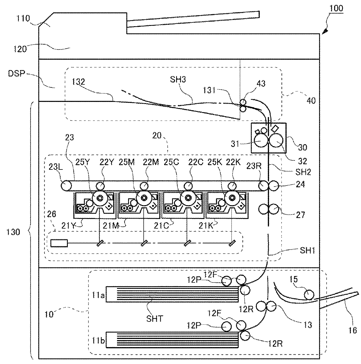
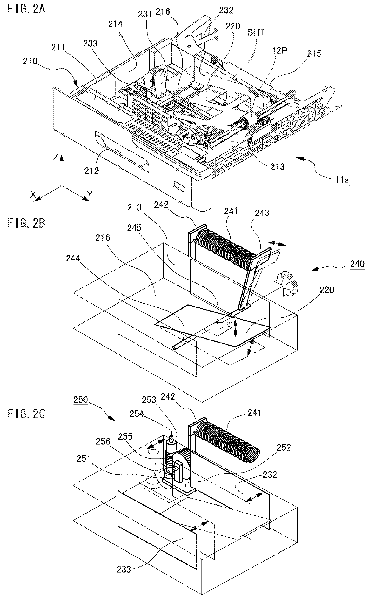
[0058]In the sheet feeder according to the first embodiment of the invention, i.e. the feeder section 10 of the MFP 100, the adjustor mechanism 250 includes the pinion 251 and rack 257. When the paper cassette 11a is pushed by a user into the housing of the printer 130, the second guide 232 reaches the specific point X=XSP on the trajectory caused by the backward motion of the paper cassette 11a, and at the same time, the pinion 251 engages with the leading tooth 258 of the rack 257. Accordingly, while the paper cassette 11a is pushed by the user from the opened position, which is out of the housing of the printer 130, to the closed position, which is in the housing, the pinion 251 travels with rotating on the teeth of the rack 257 by the user's force pushing the paper cassette 11a from the time the second guide 232 reaches the specific point X=XSP. Then, by the torque of the pinion 251, the transmission mechanism 254-256 swings the supporting lever 242 and ...

second embodiment

Merit of Second Embodiment

[0087]In the sheet feeder according to the second embodiment of the invention, i.e. the feeder section 10 of the MFP 100, the adjustor mechanism 350 includes the movable reel 351 and the fixed reel 357. When the paper cassette 11a is pushed by a user into the housing of the printer 130, the second guide 232 reaches the specific point X=XSP on the trajectory along which the second guide 232 travels caused by the backward motion of the paper cassette 11a, and at the same time, the fixed reel 357 unreels a full length of the wire 358. Accordingly, while the paper cassette 11a is pushed by the user from the opened position, which is out of the housing of the printer 130, to the closed position, which is in the housing, the wire 358 is unreeled from the movable reel 351 by the user's force pushing the paper cassette 11a from the time the second guide 232 reaches the specific point X=XSP. Then, by the torque of the movable reel 351, the transmission mechanism 254...


PUM


Abstract

In a paper cassette, a guide slides on a tray to place a sheet at a proper position. A lift mechanism uses a restoring force of an elastic member to push up the tray and make the sheet on the tray approach a pickup roller. When the paper cassette is pushed by a user from an opened position, which is out of the housing of a printer, to a closed position, which is in the housing, an adjuster mechanism mechanically converts a force of the user pushing the paper cassette to the restoring force of the elastic member from a time the guide reaches a specific point on a trajectory along which the guide travels together with the paper cassette, thus adjusting the strength of the restoring force continuously to a distance by which the guide overruns the specific point.

Description

CROSS-REFERENCE TO RELATED APPLICATIONS[0001]This application claims priority to Japanese Patent Application No. 2017-051642, filed, Mar. 16, 2017, the entire contents of which are hereby incorporated by reference in their entirety.BACKGROUND1. Technical Field[0002]The invention relates to sheet feeders, and in particular, mechanism of adjusting pressure for feeding sheets.2. Related Art[0003]“Sheet feeder” means a device automatically feeding sheets such as documents or printing paper to a machine processing the sheets such as a printer, copier, scanner, fax machine, or finisher. Sheet feeders are in general equipped with paper cassettes and pickup or feed rollers, which are hereinafter referred to as “pickup rollers.” Each paper cassette has an inner space in which sheets to be fed can be stacked. Pickup rollers rotate with their outer circumferential surfaces contact with the top of a sheaf of the sheets, thus separating each sheet from the sheaf and transmitting it to a conveyan...

Claims


Application Information

Patent Timeline
Patent Type & Authority Applications(United States)
IPC IPC(8): B65H5/06B65H3/06G03G15/00
CPCB65H5/06B65H3/0684G03G15/6502G03G15/6529B65H1/12B65H3/06B65H5/062B65H2701/1131B65H2801/03G03G15/6511B65H1/266B65H2405/12B65H2511/12B65H2511/20B65H2515/34B65H2402/54B65H2220/01B65H2220/04B65H2220/02B65H9/101B65H2403/41B65H2405/114
Inventor DOSHIDA, YUKITOMIYASU, MASANOBUSAWANO, SHIGERU
Owner KONICA MINOLTA INC
Why Eureka
Try Eureka