Porro prism stabilized laser system

a laser system and prism technology, applied in the field of lasers, can solve the problems of very narrow alignment tolerance and high cost of current laser systems, and achieve the effects of low cost, narrow alignment tolerance, and increased laser system alignment toleran

Inactive Publication Date: 2018-09-20
BAE SYST INFORMATION & ELECTRONICS SYST INTERGRATION INC
View PDF5 Cites 4 Cited by
  • Summary
  • Abstract
  • Description
  • Claims
  • Application Information

AI Technical Summary

Benefits of technology

[0005]It has been recognized that current laser systems are costly and have very narrow alignment tolerances. In certain embodiments of the laser system of the prese...

Problems solved by technology

It has been recognized that current laser system...

Method used


Image

  • Porro prism stabilized laser system
  • Porro prism stabilized laser system
  • Porro prism stabilized laser system

Examples


Embodiment Construction

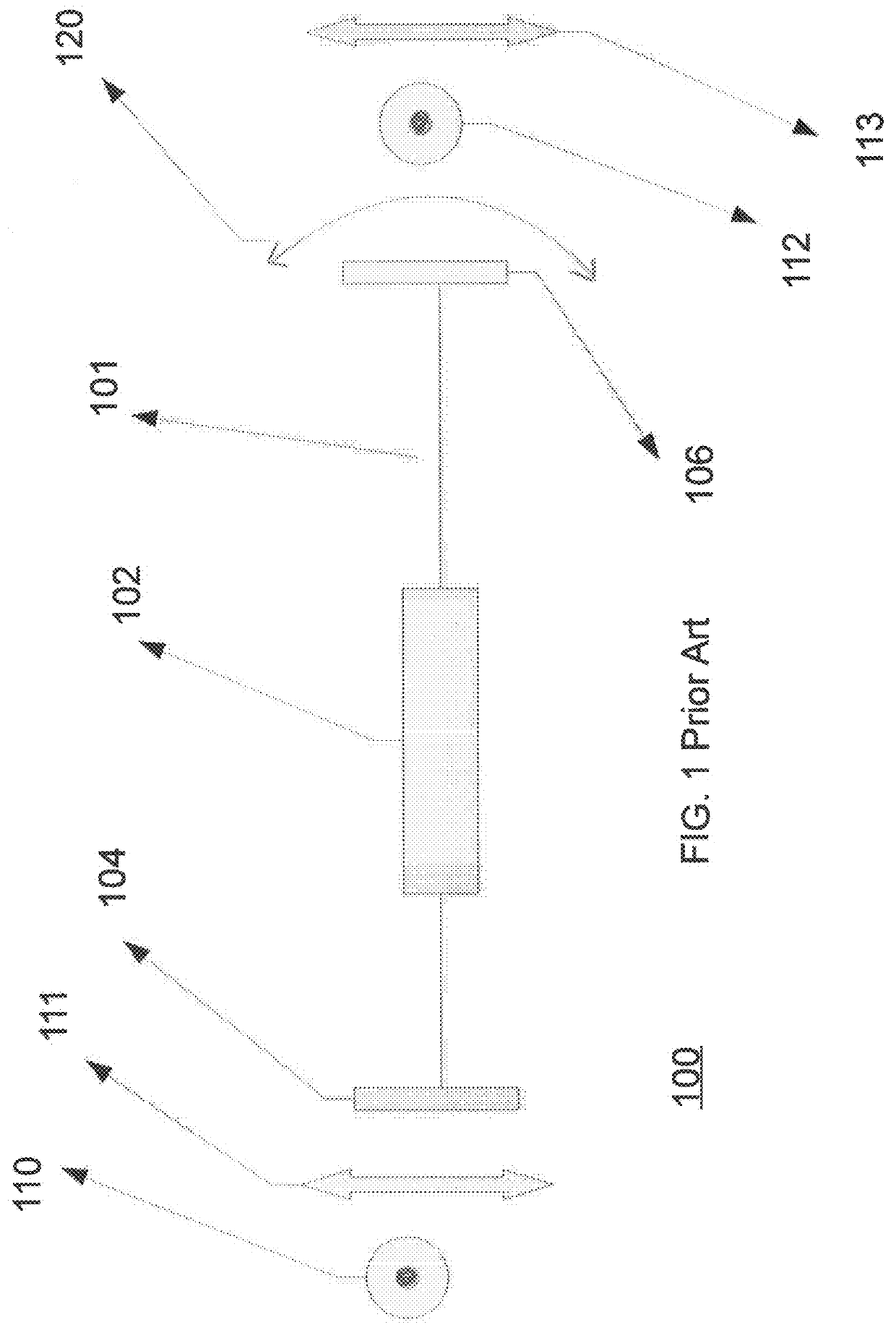
[0014]Current q-switch laser systems are designed in a linear fashion. Typical components include a partial reflector, a gain material, and an oscillating mirror spinning on a motor. The linear fashion design requires long cavities and tight tolerances between the partial reflector and the oscillating mirror. The difficulty of achieving this tight tolerance traditionally drives the cost of the device up. The tight tolerance also traditionally lowers the overall reliability of the device. In current systems, the oscillating mirror acts as a Q-switch.

[0015]It is understood that Q-switching is achieved when some type of variable attenuator is placed inside a laser's optical resonator. When the attenuator is functioning, light which leaves the gain medium does not return, and lasing cannot begin. This attenuation inside the cavity corresponds to a decrease in the quality factor or “Q-factor” of the optical resonator. This variable attenuator is commonly called a “Q-switch.”.

[0016]Typica...


PUM


Abstract

A porro prism stabilized q-switched laser system including a gain material, a partial reflector optically connected to the gain material, an oscillating mirror operably connected to the gain material, and a porro prism optically connected to the oscillating mirror. The system has a first path located between the partial reflector and the oscillating mirror, and a second path located between the oscillating mirror and the porro prism. The stabilized laser system having larger alignment tolerances making for more stable and less expensive systems. The stabilized laser system having a shorter cavity length than traditional q-switched laser systems.

Description

CROSS REFERENCE TO RELATED APPLICATIONS[0001]This Application claims the benefit of U.S. Provisional Application No. 62 / 257,382, filed Nov. 19, 2015, the contents of which are incorporated by reference herein in their entirety.FIELD OF THE DISCLOSURE[0002]The present disclosure relates to lasers and more particularly to the use of prisms to stabilize lasers.BACKGROUND OF THE DISCLOSURE[0003]Current q-switch laser components are designed in a linear fashion. The current laser components include a partial reflector, a gain material, and an oscillating mirror. The linear fashion design requires tight tolerances between the partial reflector and the oscillating mirror. The difficulty of achieving this tight tolerance traditionally drives the cost of the device up. The tight tolerance also traditionally lowers the overall reliability of the device. Current systems also require that the cavity length remain long, which reduces the stability of the cavity.[0004]In contrast, one embodiment ...

Claims


Application Information

Patent Timeline
IPC IPC(8): H01S3/136H01S3/123H01S3/081
CPCH01S3/136H01S3/123H01S3/0811H01S3/091H01S3/0815H01S3/094076H01S3/125
Inventor CHOINIERE, MICHAEL J.DEGTIAREV, EGOR V.
Owner BAE SYST INFORMATION & ELECTRONICS SYST INTERGRATION INC
Why Eureka
Try Eureka