Supercharge Your Innovation With Domain-Expert AI Agents!

Measuring system and method with digital quiet zone

a technology of measuring system and quiet zone, applied in the direction of transmission, instruments, electrical equipment, etc., can solve the problems of large scale implementation, inaccurate measurements, and high cost, and achieve the effect of controlling the measuring environment and simple implementation

Active Publication Date: 2018-09-20
ROHDE & SCHWARZ GMBH & CO KG
View PDF4 Cites 2 Cited by
  • Summary
  • Abstract
  • Description
  • Claims
  • Application Information

AI Technical Summary

Benefits of technology

The invention is a devices that can measure interference signals. The device has a generator that creates a calm area to measure interference. The generator can move the calm area to provide flexibility in measuring. The device can also produce multiple interference signals at the same time to simulate challenging conditions for testing the device.

Problems solved by technology

This approach though is disadvantageous, since very large measurement setups are required, in order to reach far-field conditions.
This leads to inaccurate measurements, though.
Such planewave converters result in a very large scale implementation and are very costly.

Method used


Image

  • Measuring system and method with digital quiet zone
  • Measuring system and method with digital quiet zone
  • Measuring system and method with digital quiet zone

Examples


Embodiment Construction

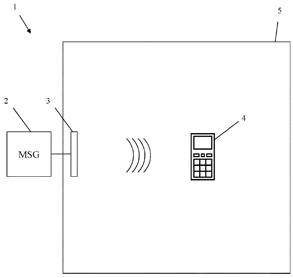
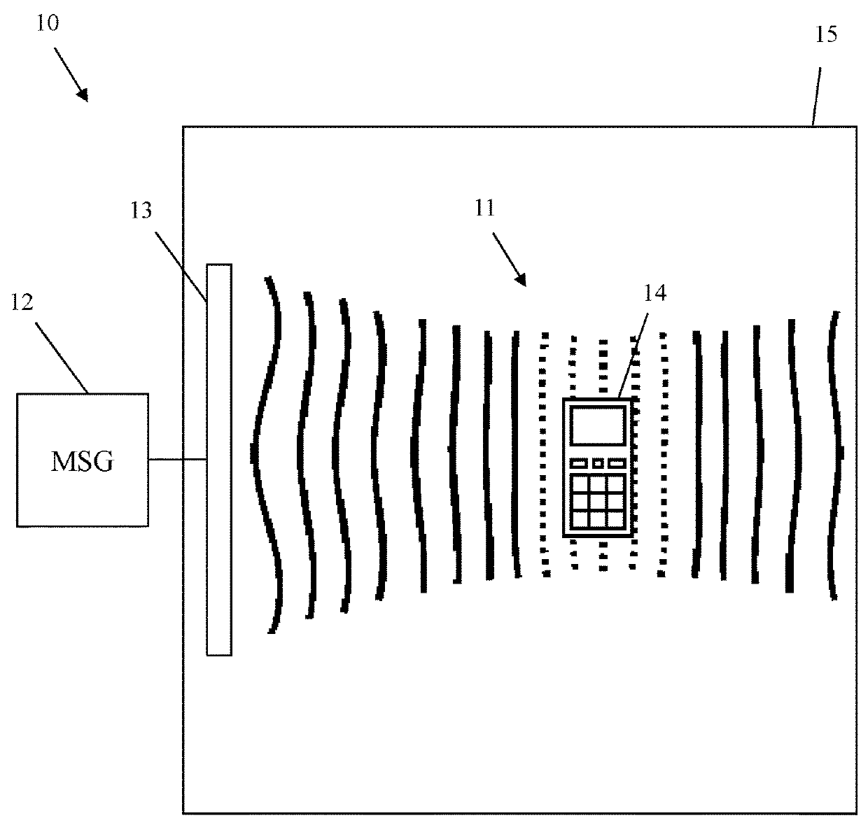
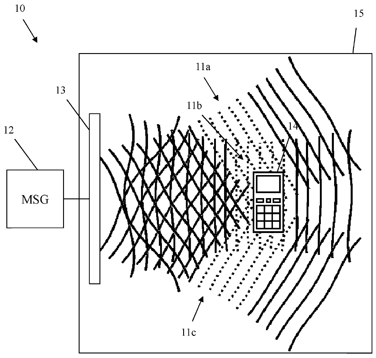
[0038]First, we demonstrate the underlying problem along FIG. 1. Along FIG. 2-FIG. 6, different embodiments of the inventive measuring system are explained with regard to their construction and function in detail. Along FIG. 7, finally the function of an embodiment of the inventive measuring method is shown. Similar entities and reference numbers in different figures have been partially omitted.

[0039]In FIG. 1, an exemplary measuring system 1 is shown. A measuring device 2 is connected to a measuring antenna 3. The measuring antenna 3 is arranged in an anechoic chambers, while the measuring device 2 is arranged outside.

[0040]Moreover, in the anechoic chamber 5, a device under test 4 is arranged. The device under test 4 is arranged in line of sight of the measuring antenna 3. Although the anechoic chambers reduce reflections on its walls to a great degree, such reflections still exist. This results in a reduced measuring accuracy. More importantly though, the anechoic chamber 5 is us...


PUM


Abstract

A measuring system for measuring properties of a device under test over the air comprises an antenna array, adapted to receive first measuring signals from the device under test, a measuring device adapted to process the first measuring signals received by the antenna array, and to generate second measuring signals and transmit them to the device under test, using the antenna array. The measuring device comprises a quiet zone generator, which is adapted to perform a beamforming of the first measuring signals after reception by the antenna array. It is preferably also adapted to perform a beamforming on the second measuring signals before transmission by the antenna array. The quiet zone generator is adapted to apply the beamforming, so that at least one adjustable quiet zone is achieved.

Description

PRIORITY[0001]This application claims priority of European patent application EP 17 161 516.4 filed on Mar. 17, 2017, which is incorporated by reference herewith.FIELD OF THE INVENTION[0002]The invention relates to a measuring system and measuring method for measuring properties of a device under test over the air.BACKGROUND OF THE INVENTION[0003]When performing measurements on a device under test over the air, it is important to prevent the influence of surrounding objects on the measurement. These objects can be for example the measuring antenna or the measuring device, or any other objects. This is usually done by placing the device under test a great distance away from any further objects. Thereby, far-field conditions are achieved. This approach though is disadvantageous, since very large measurement setups are required, in order to reach far-field conditions.[0004]Alternatively, measurements maybe performed under near field conditions. This leads to inaccurate measurements, th...

Claims


Application Information

Patent Timeline
Patent Type & Authority Applications(United States)
IPC IPC(8): H04B17/20G01R29/10
CPCG01R29/105H04B17/20H04B7/0617H04B7/086H04B17/0082H04B17/0085H04B17/102G01R29/0821
Inventor ROWELL, CORBETTTANKIELUN, ADAMMARKERT, DANIEL
Owner ROHDE & SCHWARZ GMBH & CO KG
Features
  • R&D
  • Intellectual Property
  • Life Sciences
  • Materials
  • Tech Scout
  • Unparalleled Data Quality
  • Higher Quality Content
  • 60% Fewer Hallucinations
Learn More