Electric motor

Inactive Publication Date: 2018-09-27
FANUC LTD
View PDF0 Cites 5 Cited by
  • Summary
  • Abstract
  • Description
  • Claims
  • Application Information

AI Technical Summary

Benefits of technology

The present invention aims to provide an electric motor with a stable bearing that allows for secure rotational balance of the inner race.

Problems solved by technology

In Japanese Laid-Open Patent Publication No. 2016-086561, since the groove is formed in the bearing support surface that supports the bearing, it is impossible to ensure adhesion between the bearing and the bearing support surface, and there is a concern that the bearing cannot be stably supported.
In order to solve the problem of Japanese Laid-Open Patent Publication No. 2016-086561, if through holes were formed in an inner race of the bearing, as in Japanese Laid-Open Utility Model Publication No. 06-045118, since the inner race undergoes rotation, there is a concern that rotational balance would be destroyed due to providing the through holes, and abnormal sounds or the like could occur.

Method used


Image

  • Electric motor
  • Electric motor

Examples


first embodiment

[Structure of the Electric Motor]

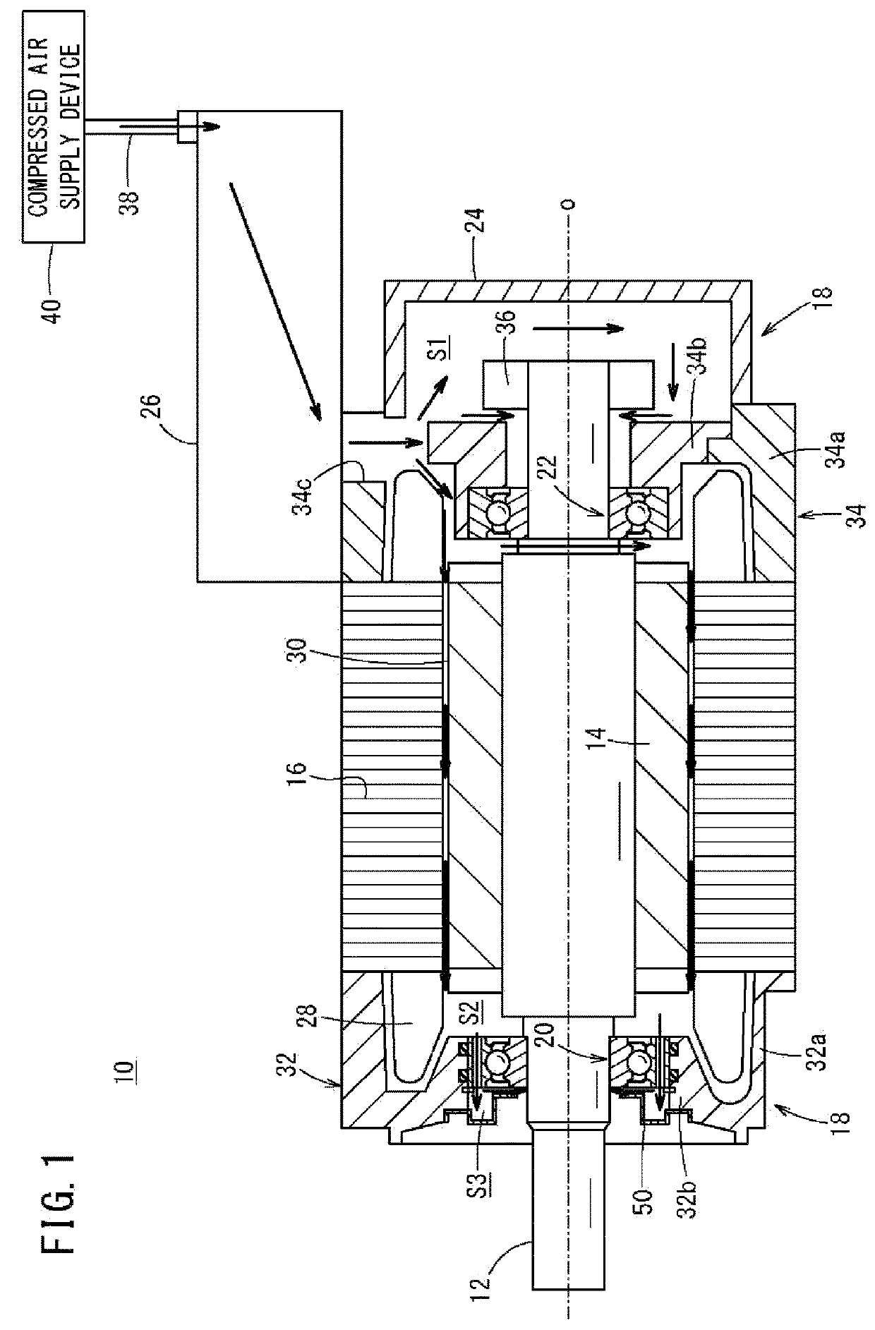
[0012]FIG. 1 is an axial cross-sectional view showing the electric motor 10 of the present embodiment. The electric motor 10 includes a shaft 12, a rotor core 14, a stator core 16, a housing 18, a first bearing 20, a second bearing 22, a rear cover 24, and a terminal box 26.

[0013]Hereinafter, a direction in which the axis of rotation O of the shaft 12 extends will be referred to as an axial direction. Further, when the electric motor 10 is observed in the state shown in FIG. 1, the left side thereof will be referred to as a front side, and the right side thereof will be referred to as a rear side. Furthermore, the direction perpendicular to the axis of rotation O and which extends radially will be referred to as a diametrical direction, and the direction of rotation about the axis of rotation O will be referred to as a circumferential direction.

[0014]The rotor core 14 is integrally and rotatably fixed to the shaft 12. The rotor core 14 is made up of ...


PUM


Abstract

An electric motor is equipped with a stator core fixed to a housing, a rotor core which rotates integrally with a shaft, and a first bearing, having an outer race with an outer circumferential surface thereof placed in abutment against the housing, and an inner race with an inner circumferential surface thereof placed in abutment against the shaft, and wherein the bearing rotatably supports the shaft with respect to the housing. Through holes is provided in the outer race, the through hole penetrating the outer race in an axial direction thereof.

Description

CROSS-REFERENCE TO RELATED APPLICATION[0001]This application is based upon and claims the benefit of priority from Japanese Patent Application No. 2017-054001 filed on Mar. 21, 2017, the contents of which are incorporated herein by reference.BACKGROUND OF THE INVENTIONField of the Invention[0002]The present invention relates to an electric motor.Description of the Related Art[0003]In Japanese Laid-Open Patent Publication No. 2016-086561, an electric motor is disclosed in which compressed air is supplied into the electric motor in order to prevent foreign matter from entering into the interior of the electric motor. The compressed air which is supplied into the electric motor passes through an axially extending groove formed in a bearing support surface of a housing, and is discharged to the exterior of the electric motor. In Japanese Laid-Open Utility Model Publication No. 06-045118, a lubricating device for a bearing is disclosed, in which the bearing includes through holes that ex...

Claims


Application Information

Patent Timeline
IPC IPC(8): H02K5/10H02K5/173H02K5/22H02K7/08H02K7/14H02K21/12
CPCH02K5/10H02K5/1732H02K5/225H02K7/083H02K7/14H02K21/12H02K5/161H02K9/04
Inventor KATSUKI, KYOUHEI
Owner FANUC LTD
Why Eureka
Try Eureka