
Portable solar photovoltaic array

a solar photovoltaic and array technology, applied in solar heat collectors, solar power plants, solar heat collectors, etc., can solve the problems of capital cost and energy generation, energy capital cost of pv array,

Active Publication Date: 2018-09-27
5B IP HLDG PTY LTD
View PDF4 Cites 4 Cited by
  • Summary
  • Abstract
  • Description
  • Claims
  • Application Information

AI Technical Summary

Benefits of technology

The present invention provides a portable and flexible PV module array that can be easily transported and erected for use. The use of a flexible connector allows for easy adjustment of the angle between the PV modules and helps to reduce the structure required to position the PV modules. The invention can be assembled from a minimum of two PV modules to a greater number, with individual PV module arrays being connected together on site using simple connectors. The PV module array can be connected in rows or end-to-end along end edges, with the number of PV modules per array being limited by the bulk of the PV array in the closed condition.

Problems solved by technology

The two main determinants of the cost of energy from a PV system are capital cost and energy generation.
With the exception of the PV modules themselves, the capital cost of a PV array is driven primarily by the cost of materials in the mounting structure (and therefore the complexity of it) and labour requirements for assembly and installation of the PV array.
A fixed PV array currently represents an effective compromise of cost, complexity and operational risk of the PV array with energy generation.
As this is often a roof, often the orientation is not optimal depending on which way the roof faces and the incline of the roof.
The downside though is the reduced energy generation due to the non-optimal fixed orientation.
Until recently, the cost benefit of the reduced structural requirements did not justify the reduced energy generation, however as PV module cost continues to fall, this balance has changed and in certain applications the EW approach can result in a lower cost of energy than conventional fixed PV arrays.
These systems are typically more expensive than a conventional fixed or EW PV array and have PV modules mounted to a complex sub-structure which includes articulated joints for unfolding the array of modules.
Portable systems of the second group of products are costly and therefore do not provide low cost of energy.
They are therefore typically only used in bespoke applications which can justify the added cost necessary to achieve the desired portability of the PV system.

Method used


Image

  • Portable solar photovoltaic array
  • Portable solar photovoltaic array
  • Portable solar photovoltaic array

Examples


Embodiment Construction

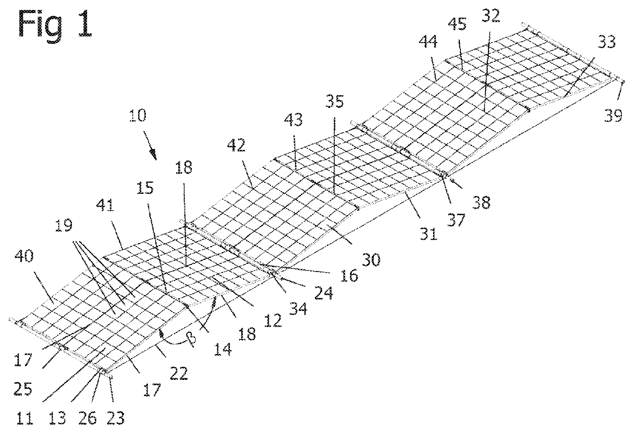
[0049]FIG. 1 is a perspective view of a portable PV array 10 according to one embodiment of the invention and is shown in an open or operational condition in which modules of the array are disposed in a triangular configuration to form an EW array of the kind described above.

[0050]The array 10 includes a first planar PV module 11 and a second planar PV module 12. All of the modules described herein will have the same construction which is rectangular and planar. The first and second modules 11 and 12 form part of a greater or larger PV array 10, but discussion will firstly focus on the modules 11 and 12 only.

[0051]Each of the modules 11 and 12 are of rectangular configuration, so that each defines a generally rectangular edge, the dimensions of which are about the same for each module 11 and 12. The edges comprise a pair of substantially parallel end edges 13 and 14 of the module 11 and end edges 15 and 16 of the module 12, and side edges 17 and 18. It can be seen, in particular wit...


PUM


Abstract

A portable PV module array, the modules being connected along adjacent end edges and being foldable relative to each other about the connected end edges between a closed condition and an open condition, whereby: in the closed condition, the PV modules are stacked together in a generally parallel and close facing relationship with the edges of the PV modules in general alignment, and in the open condition, the PV modules are disposed at an angle to each other so that the PV module array defines triangular configuration, and foldable movement of the PV modules from the closed condition to the open condition being restricted against movement beyond the open condition by a flexible connector that connects with a connection point associated with each of the PV modules of the PV module array and that is tensioned in the open condition and that is slack in the closed condition.

Description

TECHNICAL FIELD[0001]This invention relates to portable or redeployable arrays of solar photovoltaic (PV) modules for the purpose of power generation.BACKGROUND OF INVENTION[0002]Solar PV modules are well known as devices that convert light energy (electromagnetic radiation) directly into usable electric energy via a photoelectric effect. The process of conversion is well known. Solar PV modules can be formed as mountable panels and in that form, the modules have been installed extensively in the domestic and commercial markets, usually on the roofs of domestic dwellings and commercial buildings, to supplement electricity supply from the normal grid supply, or to feed back into the normal grid supply. PV modules comprise a plurality of PV cells that are connected electrically and physically in various configurations to form the PV module (or ‘solar panel’), while the module also comprises structural support and environmental encapsulation of the PV cells.[0003]To form a PV system fo...

Claims


Application Information

Patent Timeline
Patent Type & Authority Applications(United States)
IPC IPC(8): H02S30/20H02S10/40H02S40/36
CPCH02S30/20H02S10/40H02S40/36F24S2030/16Y02E10/50H01L31/05
Inventor TEHAN, EDENMCGRATH, CHRISTOPHER
Owner 5B IP HLDG PTY LTD
Learn More