Multi-shaft kneading machine

a kneading machine and multi-shaft technology, applied in the direction of mixing, transportation and packaging, rotary stirring mixers, etc., can solve the problem of not being able to ensure a sufficient range for adjusting the degree of kneading, and achieve the effect of reducing the area of the channel and ensuring the degree of adjusting

Active Publication Date: 2018-10-04
JAPAN STEEL WORKS LTD
View PDF2 Cites 0 Cited by
  • Summary
  • Abstract
  • Description
  • Claims
  • Application Information

AI Technical Summary

Benefits of technology

[0007]The object of the present invention is to provide a multi-shaft kneading machine that is able to sufficiently limit the channel and thereby ensure a sufficient range for adjusting the degree of kneading.
[0009]In the present invention, the pair of gate rods has the small diameter parts, and the small diameter parts are in contact with each other. Thus, when the gate rods are rotated to the minimum degree-of-opening positions, the first contact surfaces can be positioned close to each other. As a result, the area of the channel can be reduced at the minimum degree-of-opening position.
[0010]According to the present invention, a multi-shaft kneading machine can be provided that is able to sufficiently limit the channel and thereby ensure a sufficient range for adjusting the degree of kneading.

Problems solved by technology

Since the channel cannot be sufficiently limited, it is impossible to ensure a sufficient range for adjusting the degree of kneading.

Method used


Image

  • Multi-shaft kneading machine
  • Multi-shaft kneading machine
  • Multi-shaft kneading machine

Examples


Embodiment Construction

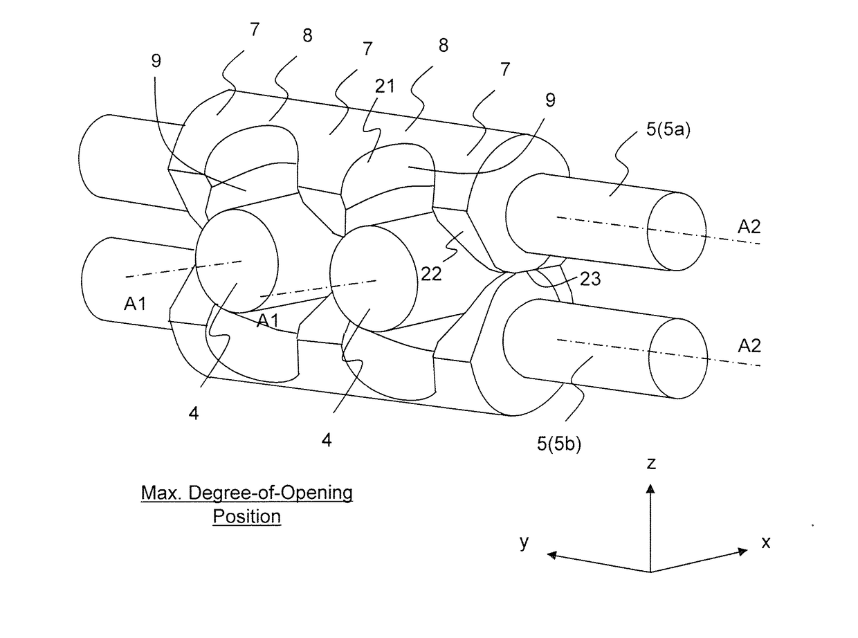
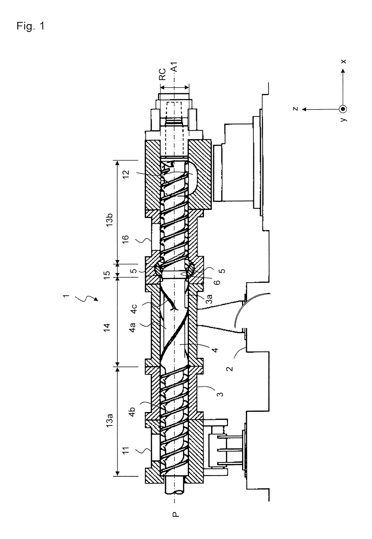
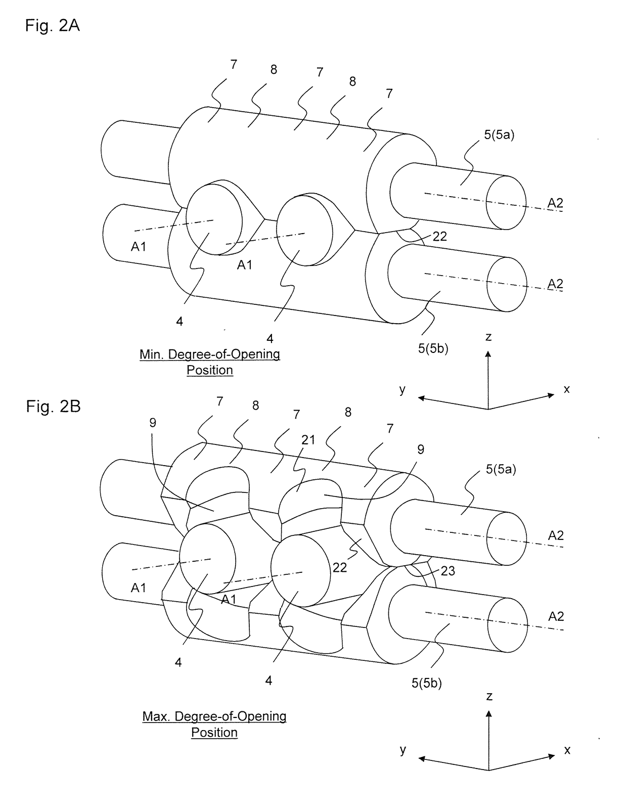
[0038]An embodiment of a multi-shaft kneading machine of the present invention will be described with reference to the drawings. An embodiment of a biaxial kneading machine will be described here, but more generally, the present invention can be applied to a multi-shaft kneading machine having a plurality of screws. In the following description and figures, the direction in which the screws extend or the direction of first axis of rotation A1 is referred to as the x-direction. The direction in which gate rods 5 extend or the direction of second axis of rotation A2 is referred to as the y-direction. The direction that is orthogonal both to the x-direction and to the y-direction is referred to as the z-direction. The z-direction corresponds to the vertical direction. Furthermore, a plane that contains first axis of rotation A1 and that has a normal line in the z-direction is referred to as reference plane P.

[0039]Moreover, in this description, the terms “first to third contact surface...


PUM

PropertyMeasurementUnit
areaaaaaaaaaaa
diameteraaaaaaaaaa
radius of curvatureaaaaaaaaaa

Abstract

A multi-shaft kneading machine includes a channel and two screws rotatable around first axes of rotation. A pair of gate rods sandwich the two screws and are rotatable around second axes of rotation. Each of the pair of gate rods has two recess parts that form respective spaces through which the two screws penetrate. Each of the pair of gate rods has a first contact surface, which comes into surface contact with a screw when a gate rod is rotated to a minimum degree-of-opening position. Large diameter parts are fitted into the groove of the cylinder, and a small diameter part have a radius of curvature equal to half a distance between two second axes of rotation and smaller than a radius of curvature of the large diameter parts. The small diameter parts of the pair of gate rods are in contact with each other.

Description

TECHNICAL FIELD[0001]The present invention relates to a multi-shaft kneading machine, and particularly to the structure of a gate rod used in a gate part.BACKGROUND ART[0002]A multi-shaft kneading machine is known that performs various kinds of processing that is aimed at homogenizing, modifying the properties of and adding materials to synthetic resin material. A biaxial kneading machine described in Patent Literature 1, which is an example of the multi-shaft kneading machine, has a cylinder having an inner space and two screws that extend in parallel with each other in the cylinder. The processing mentioned above is performed by the two screws rotating in the same direction or in opposite directions. Synthetic resin material is supplied from a supply port of the multi-shaft kneading machine, is conveyed by a conveying part, is kneaded by a kneading part, and is then discharged from an ejection port.[0003]A gate part that adjusts the degree of kneading is provided on the outlet sid...

Claims


Application Information

Patent Timeline
Patent Type & Authority Applications(United States)
IPC IPC(8): B01F7/08B29B7/46B29C48/425B29C48/67
CPCB01F7/082B29B7/46B01F2215/0049B29B7/488B29C48/03B29C48/2552B29C48/268B29C48/404B29C48/425B29C48/435B29C48/575B29C48/686B01F27/722B01F2101/2805
Inventor HAMADA, TAKUYAIKEYA, MANABUISHIKAWA, MAKOTOKODATE, KAZUHIROYAMAZAWA, TAKAYUKITAKAMOTO, SEIJI
Owner JAPAN STEEL WORKS LTD
Why Eureka
Try Eureka