Fluid ejection device, printhead, printer, and method for manufacturing the ejection device

Active Publication Date: 2018-10-04
STMICROELECTRONICS SRL
View PDF2 Cites 10 Cited by
  • Summary
  • Abstract
  • Description
  • Claims
  • Application Information

AI Technical Summary

Problems solved by technology

Pressure waves are thus generated, during use, towards the reservoir, and within the fluid contained in the reservoir itself, which causes a disturbance during the operative steps (loading of the fluid towards chamber 10 and recirculation of the fluid towa

Method used


Image

  • Fluid ejection device, printhead, printer, and method for manufacturing the ejection device
  • Fluid ejection device, printhead, printer, and method for manufacturing the ejection device
  • Fluid ejection device, printhead, printer, and method for manufacturing the ejection device

Examples


Embodiment Construction

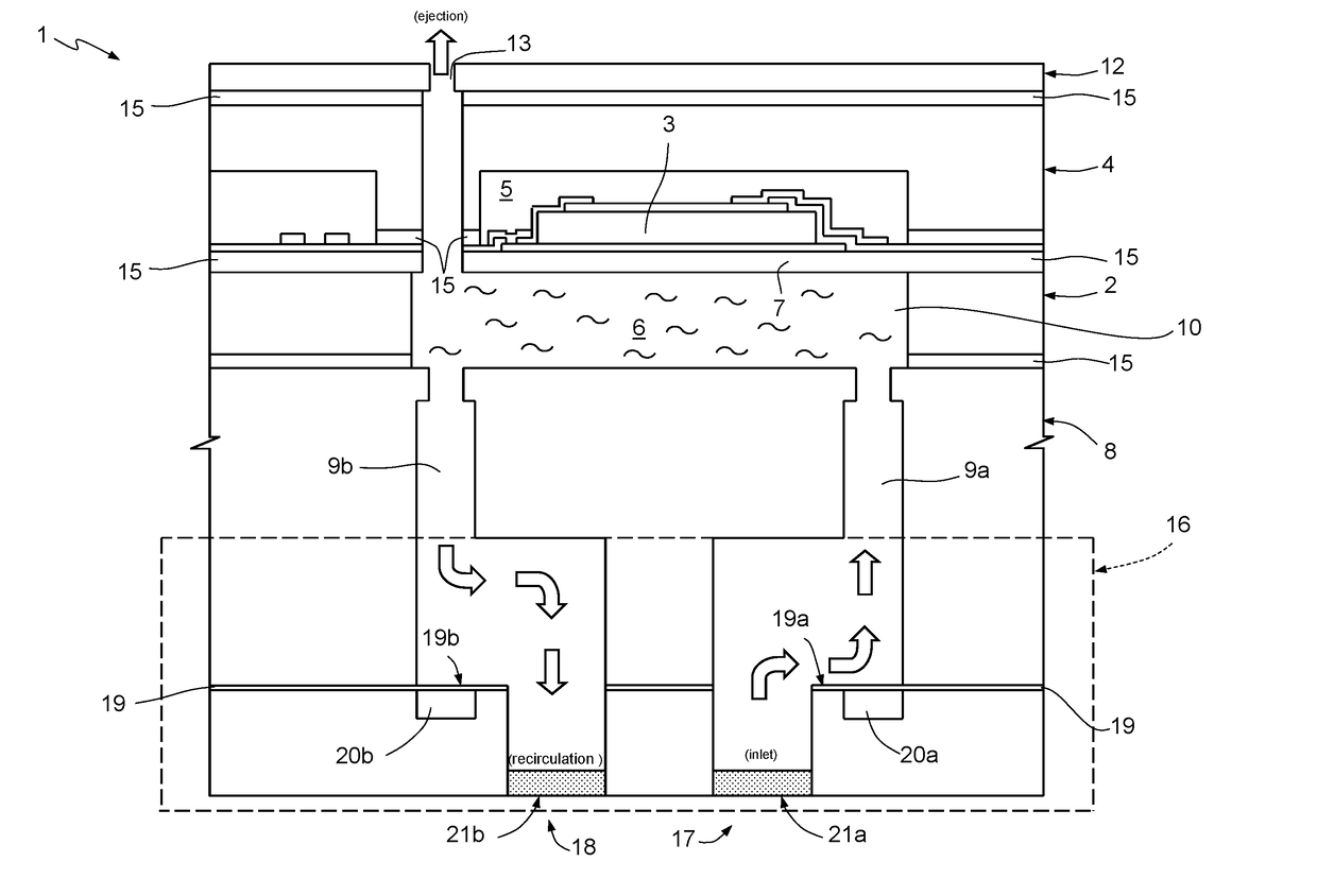
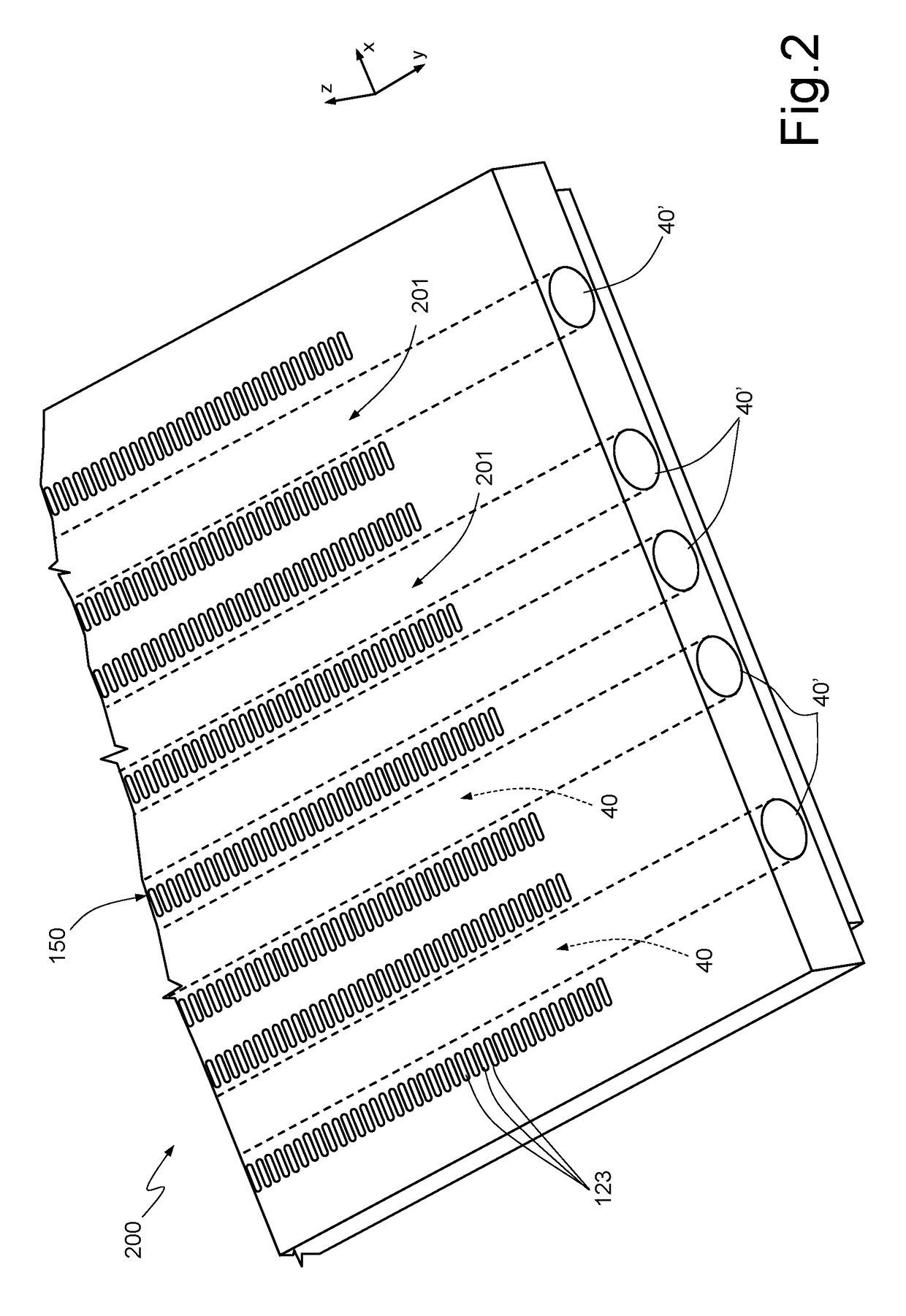
[0024]FIG. 2 shows, in perspective and in a triaxial reference system X, Y, Z, a portion of a printing device 200 including a plurality of fluid ejection elements 150 according to an aspect of the present disclosure. Each fluid ejection device 150 includes an integrated damper 201 made up of a respective membrane extending over a respective buried cavity 40. FIG. 2 shows a plurality of buried cavities 40, extending, in plan view over plane XY, sidelong with inlet holes 123 of the fluid ejection devices 150. Inlet holes 123 are capable of being coupled to a manifold and, therefore, to a fluid reservoir, to receive the fluid that is to be ejected during use. Thus, a group of fluid ejection devices 150, aligned in the same direction parallel to axis Y, shares the same integrated attenuator 201. Each buried cavity 40 is fluidically connected to the external environment by means of a respective channel 40′ which extends as a prolongation of cavity 40 along axis Y. The opening of channel ...


PUM


Abstract

Ejection device for fluid, comprising a solid body including: first semiconductor body including a chamber for containing the fluid, an ejection nozzle in fluid connection with the chamber, and an actuator operatively connected to the chamber to generate, in use, one or more pressure waves in the fluid such as to cause ejection of the fluid from the ejection nozzle; and a second semiconductor body including a channel for feeding the fluid to the chamber, coupled to the first semiconductor body, in such a way that the channel is in fluid connection with the chamber. The second semiconductor body integrates a damping cavity over which extends a damping membrane, the damping cavity and the damping membrane extending laterally to the channel for feeding the fluid.

Description

BACKGROUNDTechnical Field[0001]The present disclosure relates to a fluid ejection device with an element for reducing cross disturbances (“crosstalk”), to a printhead including the ejection device, to a printer including the printhead and to a method for manufacturing the fluid ejection device.Description of the Related Art[0002]In the current state of the art multiple types of fluid ejection device are known, in particular “inkjet” devices for printing applications.[0003]Similar devices, with suitable modifications, can also be used for the emission of various types of fluids, for example in the sphere of applications in the biological or biomedical field, for local ejection of biological material (e.g., DNA) during the manufacturing of sensors for biological analyses.[0004]An example of an ejector element with piezoelectric actuation of known type is shown in FIG. 1 and indicated with the reference number 1. A plurality of ejector elements 1 form, at least in part, a printing devi...

Claims


Application Information

Patent Timeline
IPC IPC(8): B41J2/14B05B1/02
CPCB41J2/14B05B1/02B41J2002/14346B41J2/14209B41J2/1609B41J2002/14217B41J2/055B41J2/14233B41J2/161B41J2/1623B41J2/1626B41J2/1628B41J2/1629B41J2/1631B41J2002/14403B41J2002/14419B41J2202/12B41J2/18
Inventor GIUSTI, DOMENICOFERRERA, MARCOPRELINI, CARLO LUIGIDODD, SIMON
Owner STMICROELECTRONICS SRL
Why Eureka
Try Eureka