Lighting system for a motor vehicle with active aerodynamic element

a technology of aerodynamic elements and motor vehicles, applied in the direction of fixed installation, lighting and heating equipment, transportation and packaging, etc., can solve the problems of increasing drag and instability, and achieve the effect of reducing the accumulation of fluid and grim

Active Publication Date: 2018-10-04
GM GLOBAL TECH OPERATIONS LLC
View PDF13 Cites 8 Cited by
  • Summary
  • Abstract
  • Description
  • Claims
  • Application Information

AI Technical Summary

Benefits of technology

[0002]Automotive aerodynamics is the study of aerodynamics of road vehicles. The main goals of the study are reducing drag and wind noise, minimizing noise emission, and preventing undesired lift forces and other causes of aerodynamic instability at high speeds. Additionally, the study of aerodynamics may also be used to achieve downforce in high-performance vehicles in order to improve vehicle traction, high speed stability, and cornering. The study is typically used to shape vehicle bodywork along with employing dedicated aerodynamic devices or elements for achieving a desired compromise among the above characteristics for specific vehicle use.
[0003]A spoiler is an automotive aerodynamic device intended to “spoil” unfavorable air movement across a body of a vehicle in motion, usually described as turbulence or drag. Spoilers may be fitted at the front and / or at the rear of the vehicle body. Spoilers on the front of a vehicle are often called air dams. When the vehicle is in motion, in addition to directing air flow, such air dams also reduce the amount of air flowing underneath the vehicle which generally reduces aerodynamic lift and drag.
[0004]Additionally, when the vehicle is in motion, the flow of air at the rear of the vehicle becomes turbulent and a low-pressure zone is created, increasing drag and instability. Adding an active aerodynamic element, such as a spoiler, at the rear of the vehicle body may help to delay flow separation from the body and a higher pressure zone created in front of the spoiler may help reduce lift on the vehicle body by creating a desired magnitude of downforce depending on the road speed of the vehicle. As a result, in certain positions relative to the vehicle body, such an active aerodynamic element may reduce aerodynamic drag and increase high speed stability of the vehicle due to the reduced rear lift.SUMMARY
[0013]The lens may include a hydrophobic coating configured to further diminish accumulation of fluid and grime.

Problems solved by technology

Additionally, when the vehicle is in motion, the flow of air at the rear of the vehicle becomes turbulent and a low-pressure zone is created, increasing drag and instability.

Method used


Image

  • Lighting system for a motor vehicle with active aerodynamic element
  • Lighting system for a motor vehicle with active aerodynamic element
  • Lighting system for a motor vehicle with active aerodynamic element

Examples


Embodiment Construction

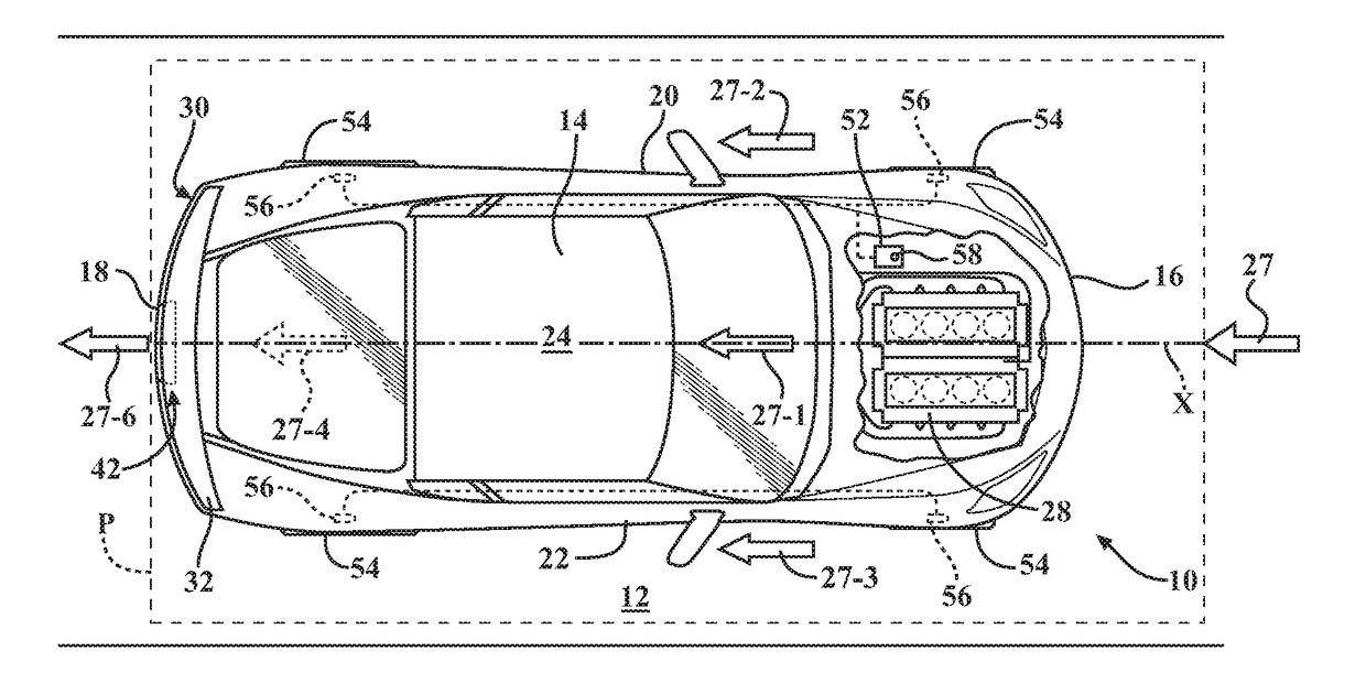
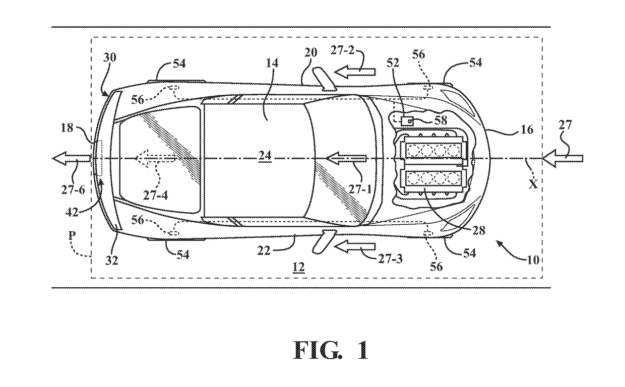
[0022]Referring to the drawings, wherein like reference numbers refer to like components, FIG. 1 shows a schematic view of a motor vehicle 10 positioned relative to a road surface 12. The vehicle 10 includes a vehicle body 14 arranged along a virtual longitudinal axis X in a body plane P that is substantially parallel to the road surface 12. The vehicle body 14 defines six body sides. The six body sides include a first body end or front end 16, an opposing second body end or rear end 18, a first lateral body side or left side 20, and a second lateral body side or right side 22, a top body portion 24, which may include a vehicle roof, and an underbody portion (not shown).

[0023]The left side 20 and right side 22 are disposed generally parallel to each other and with respect to the longitudinal axis X, and span the distance between the front end 16 and the rear end 18. The body plane P is defined to include the longitudinal axis X. A passenger compartment (not shown) of the vehicle 10 ...


PUM


Abstract

A lighting system is employed in a motor vehicle that includes a vehicle body arranged along a longitudinal axis and having a first vehicle body end configured to face oncoming ambient airflow when the vehicle is in motion relative to a road surface. The vehicle also includes a second vehicle body end opposing the first vehicle body end, and an aerodynamic-element having an aerodynamic-element body mounted to the second vehicle body end and arranged perpendicular to the longitudinal axis. The lighting system includes a light source mounted to the vehicle body and configured to direct at least one beam of light at the aerodynamic-element body. The lighting system also includes a light-reflecting feature arranged on the aerodynamic-element body and having an orientation configured to reflect the at least one beam of light along the longitudinal axis in a direction away from the first vehicle body end.

Description

INTRODUCTION[0001]The disclosure relates to a lighting system for a motor vehicle employing an active aerodynamic element.[0002]Automotive aerodynamics is the study of aerodynamics of road vehicles. The main goals of the study are reducing drag and wind noise, minimizing noise emission, and preventing undesired lift forces and other causes of aerodynamic instability at high speeds. Additionally, the study of aerodynamics may also be used to achieve downforce in high-performance vehicles in order to improve vehicle traction, high speed stability, and cornering. The study is typically used to shape vehicle bodywork along with employing dedicated aerodynamic devices or elements for achieving a desired compromise among the above characteristics for specific vehicle use.[0003]A spoiler is an automotive aerodynamic device intended to “spoil” unfavorable air movement across a body of a vehicle in motion, usually described as turbulence or drag. Spoilers may be fitted at the front and / or at...

Claims


Application Information

Patent Timeline
Patent Type & Authority Applications(United States)
IPC IPC(8): B60Q1/44B62D35/00B62D37/02B60Q1/26F21S8/10B60Q1/00
CPCB60Q1/44B62D35/007F21S43/33B60Q1/2696B60Q1/0005B62D37/02F21S43/14F21S43/15F21S43/31F21W2103/35Y02T10/88B60Q1/0035B60Q1/2661B60Q1/302
Inventor DZIURDA, ROBERT A.BOSCO, ANTHONY A.KRAPES, JAKE T.
Owner GM GLOBAL TECH OPERATIONS LLC
Why Eureka
Try Eureka