Sensor
a sensor and sensor technology, applied in the field of sensors, can solve the problem that the action cannot be detected with high accuracy, and achieve the effect of high accuracy
- Summary
- Abstract
- Description
- Claims
- Application Information
AI Technical Summary
Benefits of technology
Problems solved by technology
Method used
Image
Examples
first embodiment
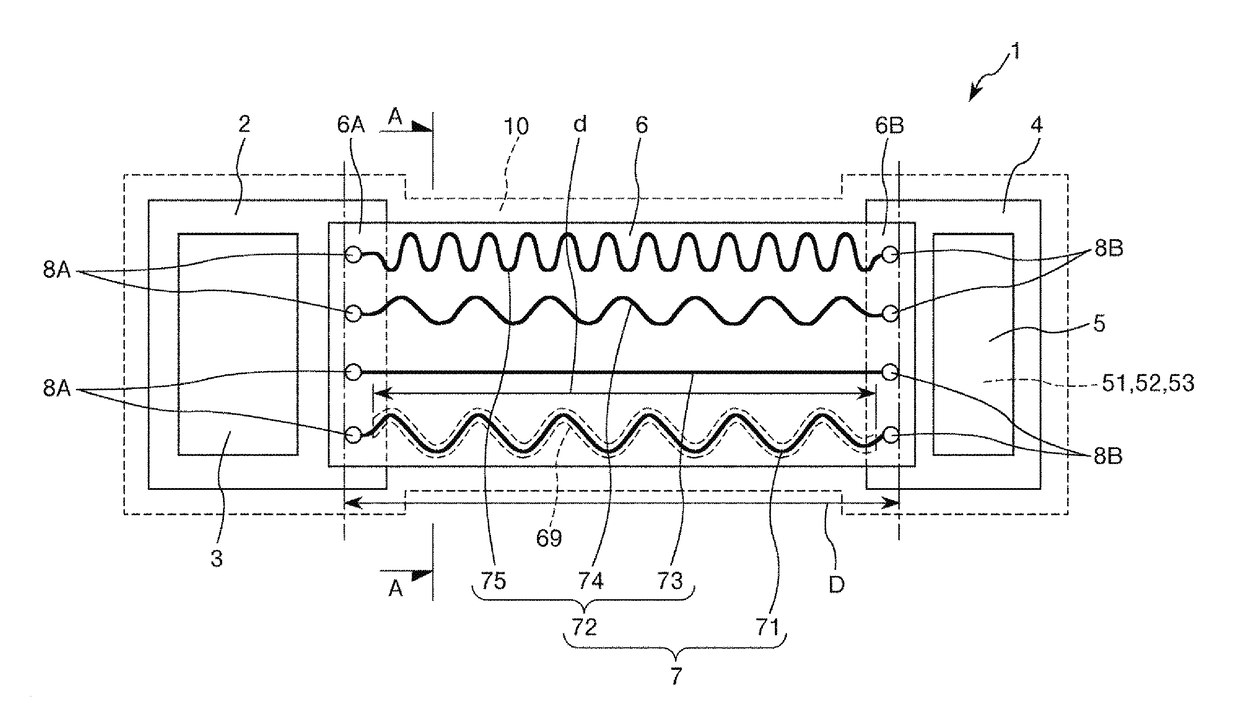
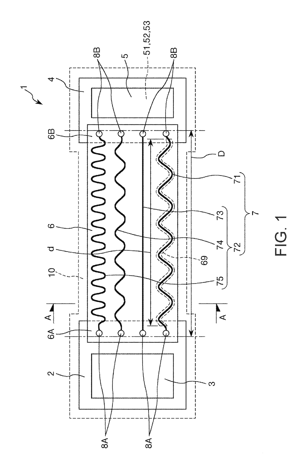
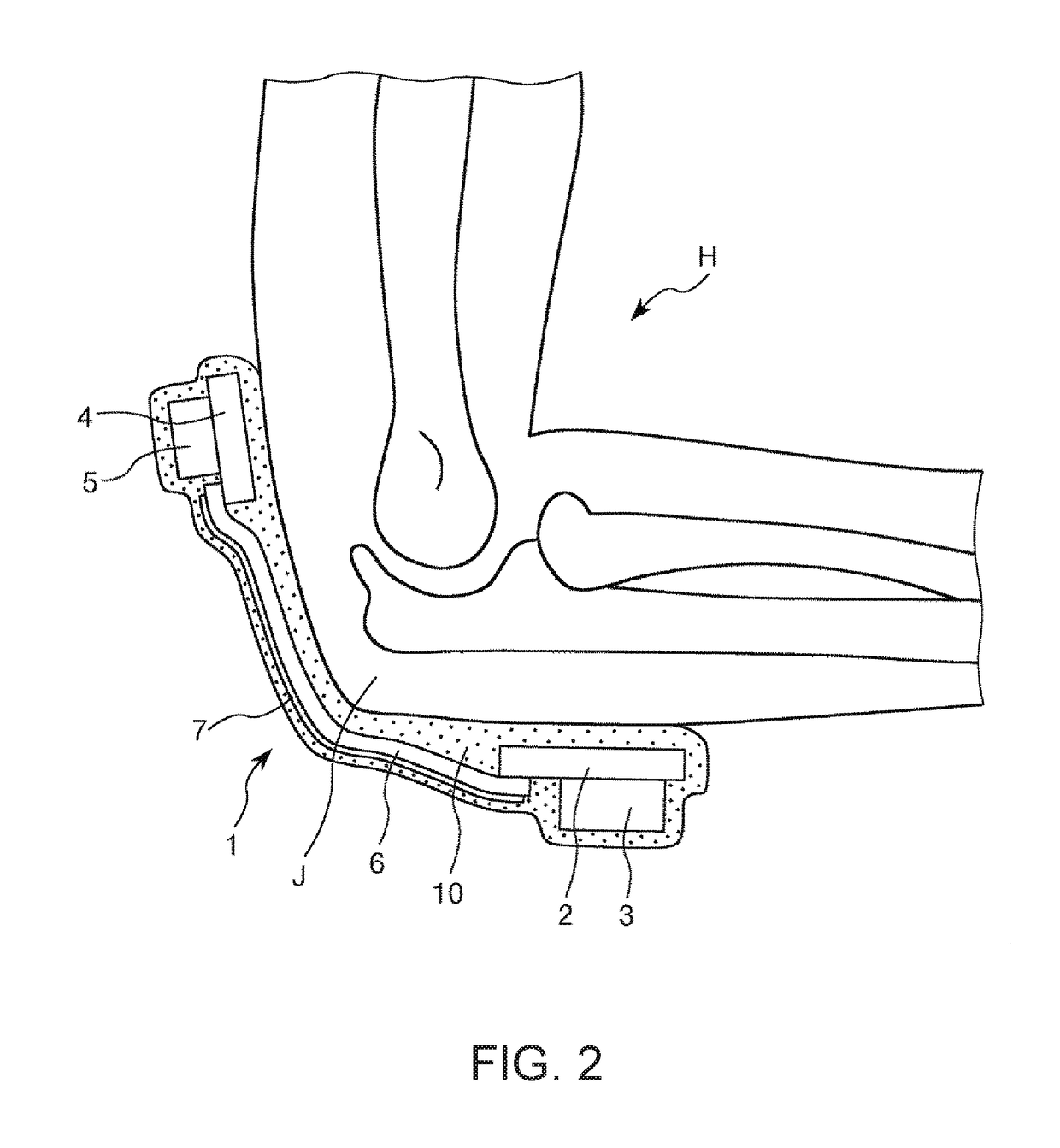
[0038]FIG. 1 is a plan view showing the sensor according to a first embodiment of the invention. FIG. 2 is a diagram showing a mounting state of the sensor shown in FIG. 1. FIG. 3 is a graph showing a relationship between an extension amount and a change rate of the resistance of each of sensing wires. FIG. 4 is a cross-sectional view along the line A-A in FIG. 1.
[0039]The sensor 1 shown in FIG. 1 is a wearable terminal used while mounted on a movable body, and available as a motion sensor for detecting a motion of the movable body. It should be noted that the movable body is not particularly limited, but there can be cited, for example, a variety of kinds of animals including humans, a variety of types of robots including joints, and a variety of moving bodies such as a vehicle and an airplane. It should be noted that in the present embodiment, for the sake of convenience of explanation, as shown in FIG. 2, the description will be presented citing the case in which the movable body...
second embodiment
[0085]FIG. 5 is a plan view showing a sensor according to a second embodiment of the invention.
[0086]The sensor according to the present embodiment is substantially the same as the first embodiment described above except the point that the configuration of the stretchable substrate 6 is different.
[0087]It should be noted that in the following description, the present embodiment will be described with a focus on the difference from the first embodiment described above, and the description of substantially the same issues will be omitted. Further, in FIG. 5, the constituents substantially identical to those of the embodiment described above are denoted by the same reference symbols.
[0088]As shown in FIG. 5, in the sensor 1 according to the present embodiment, the stretchable substrate 6 has a reference wire support section 61 for supporting the reference wire 71, and sensing wire support sections 62 for supporting the respective sensing wires 72. Further, the sensing wire support sect...
third embodiment
[0090]FIG. 6 is a plan view showing a sensor according to a third embodiment of the invention.
[0091]The sensor according to the present embodiment is substantially the same as the first embodiment described above except the point that the second substrate is omitted, and the point that the configuration of the wires 7 is different.
[0092]It should be noted that in the following description, the present embodiment will be described with a focus on the difference from the first embodiment described above, and the description of substantially the same issues will be omitted. Further, in FIG. 6, the constituents substantially identical to those of the embodiment described above are denoted by the same reference symbols.
[0093]As shown in FIG. 6, in the sensor 1 according to the present embodiment, the second substrate 4 is omitted from the configuration of the first embodiment described above, and the functional section 5 provided to the second substrate 4 is provided to the first substra...
PUM
| Property | Measurement | Unit |
|---|---|---|
| Length | aaaaa | aaaaa |
| Electrical resistance | aaaaa | aaaaa |
| Area | aaaaa | aaaaa |
Abstract
Description
Claims
Application Information
 - R&D
- Intellectual Property
- Life Sciences
- Materials
- Tech Scout
- Unparalleled Data Quality
- Higher Quality Content
- 60% Fewer Hallucinations
Browse by: Latest US Patents, China's latest patents, Technical Efficacy Thesaurus, Application Domain, Technology Topic, Popular Technical Reports.
© 2025 PatSnap. All rights reserved.Legal|Privacy policy|Modern Slavery Act Transparency Statement|Sitemap|About US| Contact US: help@patsnap.com


