
Voice processing device, voice processing method, and program

Active Publication Date: 2018-10-04
HONDA MOTOR CO LTD
View PDF15 Cites 3 Cited by
  • Summary
  • Abstract
  • Description
  • Claims
  • Application Information

AI Technical Summary

Benefits of technology

The present invention provides a device, method, and program that can accurately identify a speaker based on their unique voice. This is particularly useful in situations where the speaker's direction does not change significantly over a short time. Additionally, the invention provides speech information to each correctly identified speaker, reducing the need for editing of speech content. Finally, the invention avoids identification errors by utilizing a section where there is only one speaker in a directory and reducing the reliance on sound sources other than the speaker for identification.

Problems solved by technology

However, the sound source separation technique has a defective setting issue in that an output depends on initial inputs and various parameters used for processing.
In addition, distortion of speech voices and a decrease in a signal-to-noise (SN) ratio may occur in an output acquired according to sound source separation.
Hence, there still remains a possibility of failure of speaker identification in a section in which a plurality of speakers simultaneously speak.

Method used


Image

  • Voice processing device, voice processing method, and program
  • Voice processing device, voice processing method, and program
  • Voice processing device, voice processing method, and program

Examples


first embodiment

[0024]Hereinafter, a first embodiment of the present invention will be described with reference to the drawings.

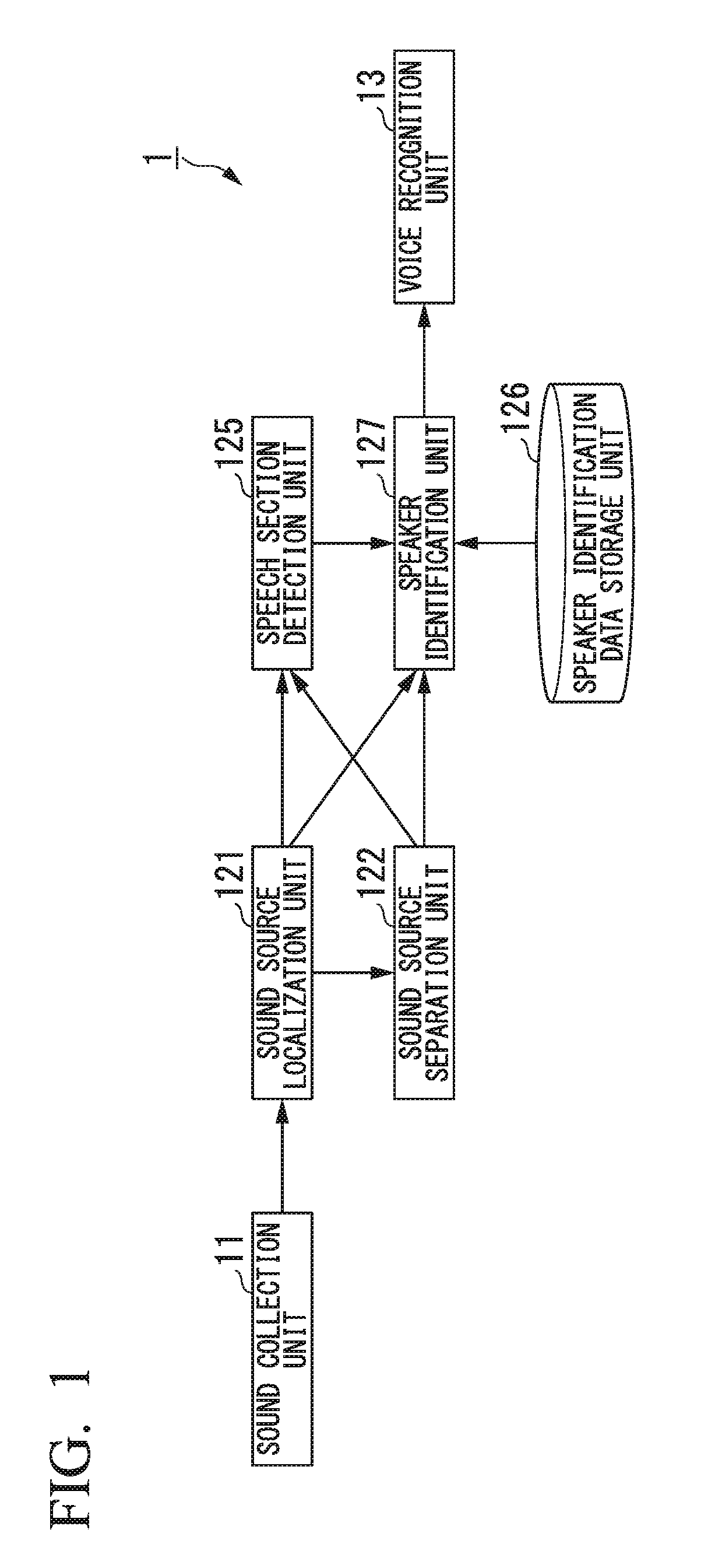
[0025]FIG. 1 is a block diagram showing an example of a configuration of a voice processing device 1 according to the present embodiment.

[0026]The voice processing device 1 includes a sound collection unit 11, a sound source localization unit 121, a sound source separation unit 122, a speech section detection unit 125, a speaker identification data storage unit 126, a speaker identification unit 127, and a voice recognition unit 13.

[0027]The sound collection unit 11 collects sound signals of N channels (N being an integer equal to or greater than 2) and outputs the collected sound signals to the sound source localization unit 121. For example, the sound collection unit 11 is a microphone array including N microphones which are arranged at different positions. Each microphone collects sound signals of one channel. The sound collection unit 11 may transmit collected sound si...

second embodiment

[0102]Next, a second embodiment of the present invention will be described. Differences between the first embodiment and the second embodiment will be mainly described in the following. Components the same as those in the first embodiment are denoted by the same reference signs and description thereof will be cited.

[0103]FIG. 4 is a block diagram showing an example of a configuration of the voice processing device 1 according to the present embodiment.

[0104]The voice processing device 1 includes the sound collection unit 11, the sound source localization unit 121, the sound source separation unit 122, the speech section detection unit 125, the speaker identification data storage unit 126, the speaker identification unit 127, an image processing unit 128, the voice recognition unit 13, and an image capturing unit 14.

[0105]The image capturing unit 14 captures an image of a surrounding object present within a predetermined visual field at each of predetermined time intervals (e.g., eve...


PUM


Abstract

A voice processing device includes: a sound source localization unit configured to determine a direction of each sound source on the basis of voice signals of a plurality of channels; a sound source separation unit configured to separate signals for respective sound sources indicating components of respective sound sources from the voice signals of the plurality of channels; a speech section detection unit configured to detect a speech section in which the number of speakers is 1 from the signals for respective sound sources; and a speaker identification unit configured to identify a speaker on the basis of the signals for respective sound sources in the speech section.

Description

CROSS-REFERENCE TO RELATED APPLICATION[0001]Priority is claimed on Japanese Patent Application No. 2017-065932 filed Mar. 29, 2017, the content of which is incorporated herein by reference.BACKGROUND OF THE INVENTIONField of the Invention[0002]The present invention relates to a voice processing device, a voice processing method, and a program.Description of Related Art[0003]Conventionally, a speaker identification technology for identifying a speaker who speaks on the basis of collected voice signals has been proposed. A speaker identification technology may be used in a situation such as a conversation or a meeting in which, among a plurality of speakers, any speaker who is speaking is identified. Characteristics of voices of speakers overlap in voice signals of one channel collected in a situation in which a plurality of speakers simultaneously speak, and thus speaker identification may fail.[0004]Accordingly, speaker identification using a signal for each sound source which indic...

Claims


Application Information

Patent Timeline
IPC IPC(8): G10L17/20G10L21/028G10L21/0232
CPCG10L17/20G10L21/028G10L21/0232G01S3/8006G10L15/26G10L17/00G10L25/78G10L21/0272G06V40/161
Inventor NAKADAI, KAZUHIROSAHATA, TOMOYUKI
Owner HONDA MOTOR CO LTD
Features
  • Generate Ideas
  • Intellectual Property
  • Life Sciences
  • Materials
  • Tech Scout
  • Unparalleled Data Quality
  • Higher Quality Content
  • 60% Fewer Hallucinations
Learn More