Method for the location of a beacon by angles of arrival

Pending Publication Date: 2018-11-15
THE SWATCH GRP RES & DEVELONMENT LTD
View PDF11 Cites 0 Cited by
  • Summary
  • Abstract
  • Description
  • Claims
  • Application Information

AI Technical Summary

Benefits of technology

[0028]These two forms of embodiment are particularly advantageous where an algorithm of the Beamforming Spatial Filtering type, as described above, is deployed for the calculation of the estimation functions for angles of arrival. The parameters required by this algorithm are in fact the phase and amplitude vectors of the incident signals on the sensors of an antenna network. The phases and amplitudes are calculated, for example, using the frequency spectra for the phase and amplitude of the signals received. Yet, it is important to distinguish the signals from noise in these frequency spectra, in order to identify the characteristic rays of the signals emitted by the beacon. Identification of the frequency drifts between the receiver

Problems solved by technology

This algorithm permits a high degree of spatial resolution, and is relatively simple to deploy, but is particularly complex in terms of calculations.
However, this technique is restricted in interior locations, in which the wave then employs multiple paths, sp

Method used


Image

  • Method for the location of a beacon by angles of arrival
  • Method for the location of a beacon by angles of arrival
  • Method for the location of a beacon by angles of arrival

Examples


Example

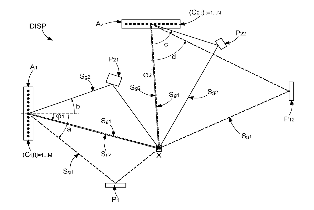
[0058]The object of the invention is the location of a beacon X in an environment which features a plurality of reflective elements, four of which being represented, for exemplary purposes, by reference symbols P11, P12, P21 and P22. In any environment, the reflective elements may be of different dimensions, as illustrated in FIG. 1.

[0059]The beacon X is configured to emit R signals (Sgi)i=1 . . . R of distinct wavelengths (λi)i=1 . . . R, where R is a whole number equal to or greater than 2. In the interests of clarity, only two signals Sg1 and Sg2, of respective wavelengths λ1 and λ2, are represented in FIG. 1. The signals (Sgi)i=1 . . . R emitted by the beacon X are reflected to a varying degree from the reflective elements, according to their wavelength. A disruptive element of dimensions close to the wavelength of a given signal will in fact specifically reflect said signal, but will only reflect a signal of a wavelength which differs substantially from its dimensions to a limi...


PUM


Abstract

A method for location of a beacon includes: executing R sequences, wherein R is a whole number equal to or greater than 2, each including reception by a first antenna network and a second antenna network of a signal originating from the beacon, wherein the signals of the R sequences are of different wavelengths; calculating a first estimation function for angles of arrival of the signal on the first antenna network and of a second estimation function for angles of arrival of the signal on the second antenna network; and executing a mutual correlation of the R first estimation functions and the R second estimation functions, for the respective determination of a first angle between the beacon and the first network, and of a second angle between the beacon and the second network.

Description

FIELD OF THE INVENTION[0001]The invention relates to the technical field of devices and methods for the location of beacons. Any device which is employed for the purposes of location, and is locatable and identifiable by appropriate means, may be called a beacon.PRIOR ART[0002]The location of a beacon by the calculation of directions of propagation of a radio-frequency signal originating from the beacon and incident on at least two antenna networks is known. This technique is known as the angle of arrival location method. In this context, numerous algorithms have been developed for the estimation of an angle of arrival of a signal on an antenna network. More precisely, these algorithms enable to calculate functions associating probabilities with angles of arrival of the signal on the antenna network.[0003]For example, the “MUSIC” (abbreviation of “Multiple Signal Classification”) algorithm is known, described by R. O. Schmidt in the article “Multiple emitter location and signal para...

Claims


Application Information

Patent Timeline
IPC IPC(8): G01S3/04G01S3/48G01S5/04G01S5/02
CPCG01S3/043G01S3/48G01S5/04G01S5/0226G01S3/04
Inventor CASAGRANDE, ARNAUD
Owner THE SWATCH GRP RES & DEVELONMENT LTD
Why Eureka
Try Eureka