Adaptive digital predistortion for polar transmitter

a technology of polar transmitter and adaptive digital, applied in the direction of digital transmission, amplifier modification to reduce non-linear distortion, high-frequency amplifier, etc., can solve the problems of system, however, not fully benefiting from the efficiencies available, and the power consumption of the transceiver is very importan

Active Publication Date: 2018-10-04
INNOPHASE
View PDF2 Cites 35 Cited by
  • Summary
  • Abstract
  • Description
  • Claims
  • Application Information

AI Technical Summary

Benefits of technology

This patent describes an improved design for a polar transmitter that can adjust its power levels based on different needs. It uses a special coding system called a binary-to-thermometer decoder which has multiple temperature settings or codes. These codes are then used by individual cells in the transmitter to determine their optimal performance. A separate power control circuit helps regulate the amount of power sent through these cells. By doing this, the transmitter can ensure consistent quality across all frequencies while maintaining efficiency. Additionally, there may be a loop delay matching circuit to improve overall timing accuracy. Overall, this new design allows for better flexibility and more precise control over the transmission process.

Problems solved by technology

The patent text discusses the use of polar transmitters to reduce power consumption in wireless communication applications, especially those powered by batteries. However, the use of efficient power amplifiers in these transmitters can result in nonlinear performance. The text references previous solutions using digital predistortion, but these solutions do not fully benefit from the efficiency of polar transmitter technology. The technical problem addressed in this patent is how to minimize power consumption while maintaining optimal amplifier performance in polar transmitters.

Method used


Image

  • Adaptive digital predistortion for polar transmitter
  • Adaptive digital predistortion for polar transmitter
  • Adaptive digital predistortion for polar transmitter

Examples


Embodiment Construction

Digital Predistortion Circuits.

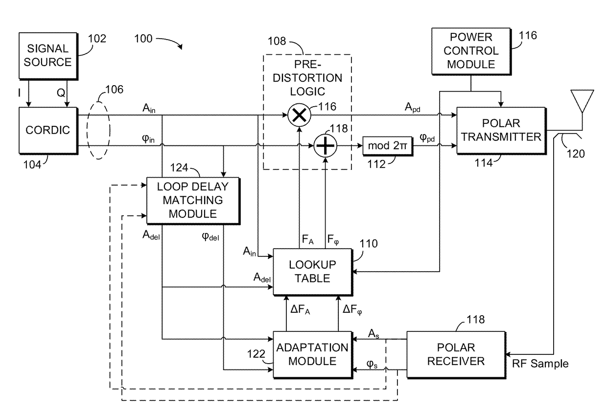
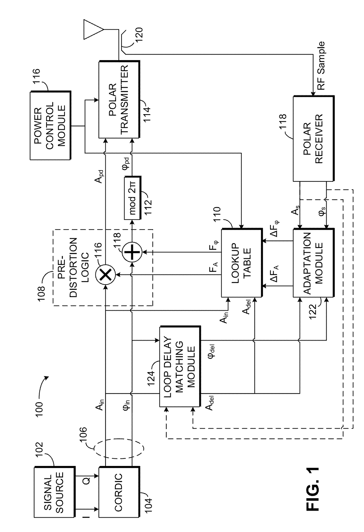
[0036]An exemplary digital predistortion circuit 100 for use with a polar transmitter is illustrated in FIG. 1. A signal source 102 is provided to generate in-phase (I) and quadrature (Q) values of a signal to be transmitted. Signal source 102 may be any source of I and Q values known to those of skill in the art, such as encoders for frequency modulated or phase-modulated radio-frequency signals, such as signals modulated using phase shift keying (PSK) or quadrature amplitude modulation (QAM). As the term is used in the present disclosure, phase-modulated signals include signals that are modulated in phase (e.g., binary phase-shift keying, quadrature phase-shift keying, 8-PSK, or 16-PSK) as well as signals that are modulated in both phase and amplitude (e.g., 16-QAM, 64-QAM, or 256-QAM). Frequency modulated signals include, among others, frequency shift keying (FSK) signals such as binary frequency-shift keying (BFSK) signals, multiple frequency-shift...


PUM


Abstract

A predistortion circuit receives an input polar signal to be transmitted, including an input amplitude signal and an input phase signal. The input polar signal is predistorted using at least one predistortion parameter selected from a lookup table. A phase-and-amplitude modulated radio-frequency signal is generated corresponding to the predistorted polar signal. A copy of the generated radio-frequency signal is provided to a polar receiver. The polar receiver is operated to generate, from the copy of the radio-frequency signal and without information relating to the generated transmit signal, a feedback polar signal including a feedback amplitude signal and a feedback phase signal. The feedback polar signal is compared to the input polar signal, the lookup table is updated in response to the comparison.

Description


Claims


Application Information

Patent Timeline
Owner INNOPHASE
Why Eureka
Try Eureka