Shaft assembly, covering or protective device, and mounting kit

a technology for shafts and components, applied in the direction of sunshade, light protection screens, door/window protective devices, etc., can solve the problems of significant temperature expansion of components used, the state in which the shaft assembly is completely or almost completely wound up, and the installation of such a shaft assembly is still very complex, so as to reduce the risk of incorrect installation and incorrect adjustment, and the effect of easy installation

Active Publication Date: 2018-10-11
ACOMAX GMBH
View PDF0 Cites 13 Cited by
  • Summary
  • Abstract
  • Description
  • Claims
  • Application Information

AI Technical Summary

Benefits of technology

[0011]In view of this, it is an object of the present disclosure to present a shaft assembly for a covering or protective device, in particular for a roller shutter, roller door or an awning, which is easy to install and which reduces the risk of incorrect installation and incorrect adjustments.

Problems solved by technology

On the other hand, however, it has been observed that the mounting of such a shaft assembly is still very complex.
However, in case of repair, there is often a state in which the shaft assembly is completely or almost completely wound up.
This may result in considerable temperature expansions in the components used, which may have a negative effect on the operating behavior.
Furthermore, it has been observed that the ease of movement of the device could be impaired, for example, by the setting behavior of buildings and / or other external influences.
However, if changes occur due to external influences, smooth running is no longer provided.
This may result in an increased wear, increased energy consumption and a reduced service life.

Method used


Image

  • Shaft assembly, covering or protective device, and mounting kit
  • Shaft assembly, covering or protective device, and mounting kit
  • Shaft assembly, covering or protective device, and mounting kit

Examples


Embodiment Construction

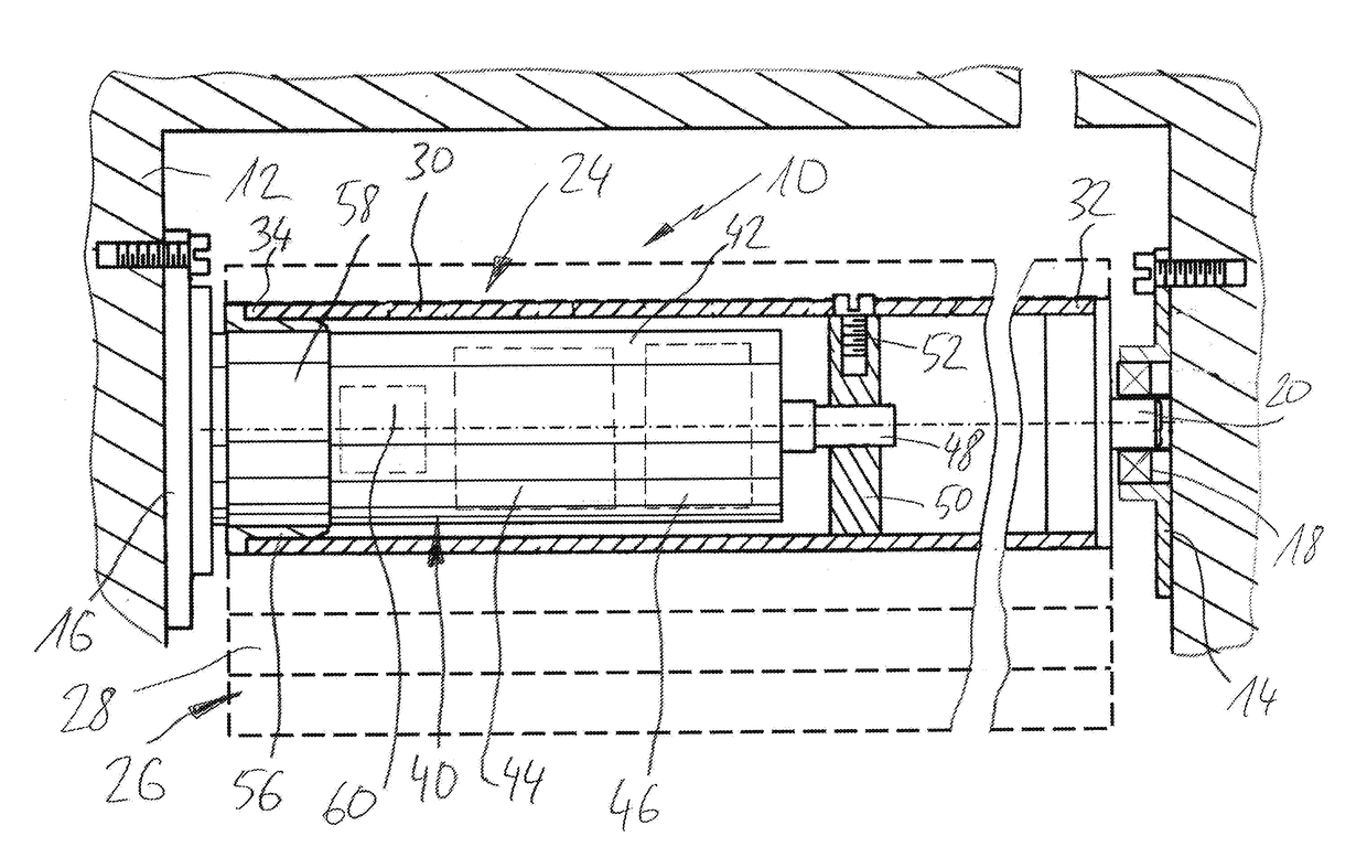
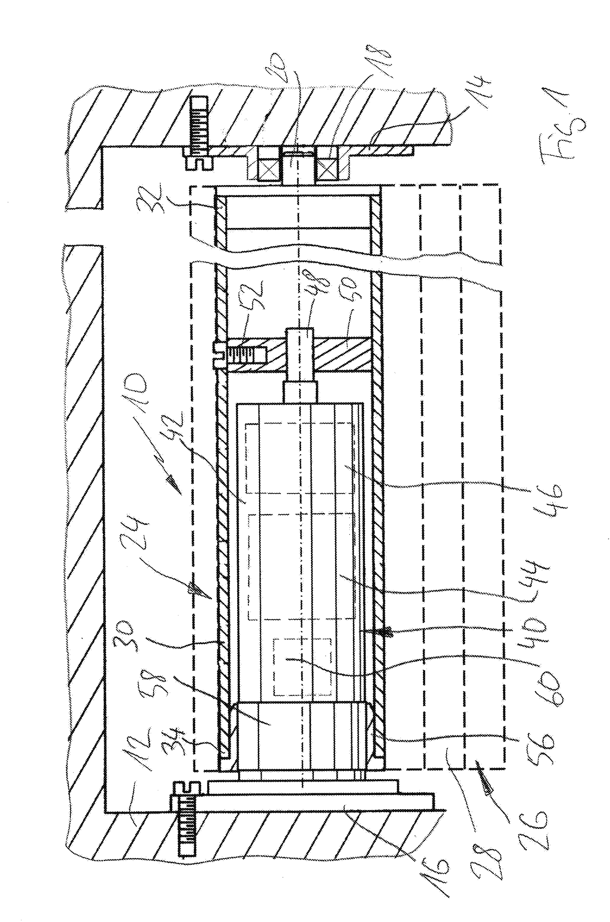
[0091]FIG. 1 illustrates with reference to a longitudinal sectional view an exemplary design of a covering device 10. The covering device 10 is designed as a roller shutter, roller door, awning or a segment door / articulated door, for example. The covering device 10 is fixedly attached to a wall 12. It goes without saying that the covering device 10 may also be mounted on the ceiling, via boxes and in a similar manner.

[0092]FIG. 1 illustrates a conventional design of the covering device 10, which is described for example in U.S. Pat. No. 5,105,871 A.

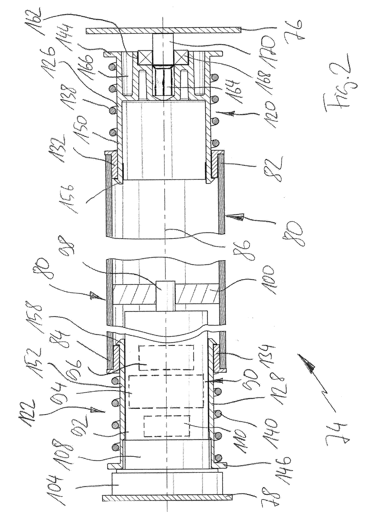
[0093]Exemplary embodiments of shaft assemblies according to the present disclosure are elucidated in detail and described with reference to FIGS. 2 to 15, wherein reference is made to the exemplary installation setting illustrated in FIG. 1, respectively.

[0094]In FIG. 1 the covering device 10 comprises a first support bearing 14 and a second support bearing 16, which are mounted on opposite walls 12 in the exemplary embodiment illustrate...


PUM


Abstract

A shaft assembly for a protective or closing device comprises a hollow-shaped hollow section body and a drive unit. The shaft assembly is arranged to be mounted between a first support bearing and a second support bearing. The hollow section body is rotatable about longitudinal axis thereof and arranged to accommodate a curtain or a panel. The drive unit is at least partially accommodated in the hollow section body. The drive unit comprises an output for rotatably driving the hollow section body. The hollow section body comprises a first end and a second end and extends between the first support bearing and the second support bearing. At least at the first end or at the second end of the hollow section body, a connecting sleeve is provided. A biasing element is arranged between the hollow section body and the connecting sleeve. The connecting sleeve is axially displaceable relative to the hollow section body against a force applied by the biasing element.

Description

CROSS REFERENCE TO RELATED APPLICATIONS[0001]This application claims priority from German patent application 10 2017 107 826.6, filed on Apr. 11, 2017. The entire content of that priority application is fully incorporated by reference herewith.BACKGROUND[0002]The present disclosure relates to a shaft assembly for a covering or protective device, in particular for a roller shutter, a roller door or an awning. The present disclosure further relates to a covering or protective device that is provided with a respective shaft assembly, and to a mounting kit for flexibly mounting a shaft assembly.[0003]GB 2,339,820 B discloses an end plug assembly for coupling a roller of an architectural covering to a mounting bracket, said end plug assembly comprising a cylindrical body engageable with an end of said roller, said body having inner and outer axial ends. and an axially extending, first central cavity, open at said outer axial end; a telescopic member, adapted for limited telescopic moveme...

Claims


Application Information

Patent Timeline
Patent Type & Authority Applications(United States)
IPC IPC(8): E06B9/68E04F10/06E05F15/00
CPCE06B9/68E04F10/0648E05F15/00E05Y2201/706E06B9/171E06B9/44E06B9/72E06B9/40E06B2009/1713E06B2009/407
Inventor WALTER-SEIFART, ROLF
Owner ACOMAX GMBH
Why Eureka
Try Eureka