
Hand-push rotating umbrella

a technology of umbrellas and umbrella frames, applied in the field of reverse folding umbrellas, can solve the problems of long assembly man-hours and not up to the production effectiveness, reduced service life, and liable deformation and damage of umbrella frames, so as to achieve stable umbrella opening state, processing and assembly faster and more convenient, and up to the economic

Inactive Publication Date: 2018-10-18
FAN JENNY
View PDF0 Cites 5 Cited by
  • Summary
  • Abstract
  • Description
  • Claims
  • Application Information

AI Technical Summary

Benefits of technology

The present invention provides an improved design for a folding umbrella that prevents the need for a snap-fit structure and reduces the risk of injury from rotation. The upper header includes a resilient sleeve to impact force and the moveable runner has extension springs to ensure a stable opening and closing state. Additionally, the invention allows the umbrella canopy to rotate to offset impact force from wind or collisions, improving safety and preventing damage to the umbrella or injury to the user. These features make the invention convenient, low cost, and easy to assemble.

Problems solved by technology

1. The umbrella is opened such that an acting force ensuring; the umbrella runner's upward going is produced through the second mounting groove pulling by the first elastic piece. Therefore, when the automatically out-turned umbrella is in the closed state, the, automatically out-turned umbrella can only be fixed in the closed state by engaging the clamping piece on the umbrella shaft together with the umbrella runner. However, because the first elastic piece has a certain pretension force, the umbrella runner would have the problem of popping open in the case of casual umbrella shaking by the user or accidental umbrella collision with some object because of the pretension force of the first elastic piece. Moreover, although the umbrella runner fixing by way of clamping piece is easy, the clamping piece is often not positioned into the stop hole on umbrella shaft during, assembly and therefore unable to be clamped within the stop hole, thus producing quality defects; and, the clamping piece can only be clamped within the stop hole on umbrella shaft by continuous manual adjustment, resulting in long assembly man-hours and not up to the production effectiveness.
2. Since the umbrella frame of the automatically out-turned umbrella is fixed by the umbrella runner, in the case of strong wind or umbrella frame end collision with some foreign object or person, the force produced by the collision and wind resistance cannot be offset or abated. Therefore, the umbrella frame is liable to deformation and damage with its service life reduced; and it may even bump into other people and the umbrella frame end may have the danger of stabbing and hurting other people.

Method used


Image

  • Hand-push rotating umbrella
  • Hand-push rotating umbrella
  • Hand-push rotating umbrella

Examples


first embodiment

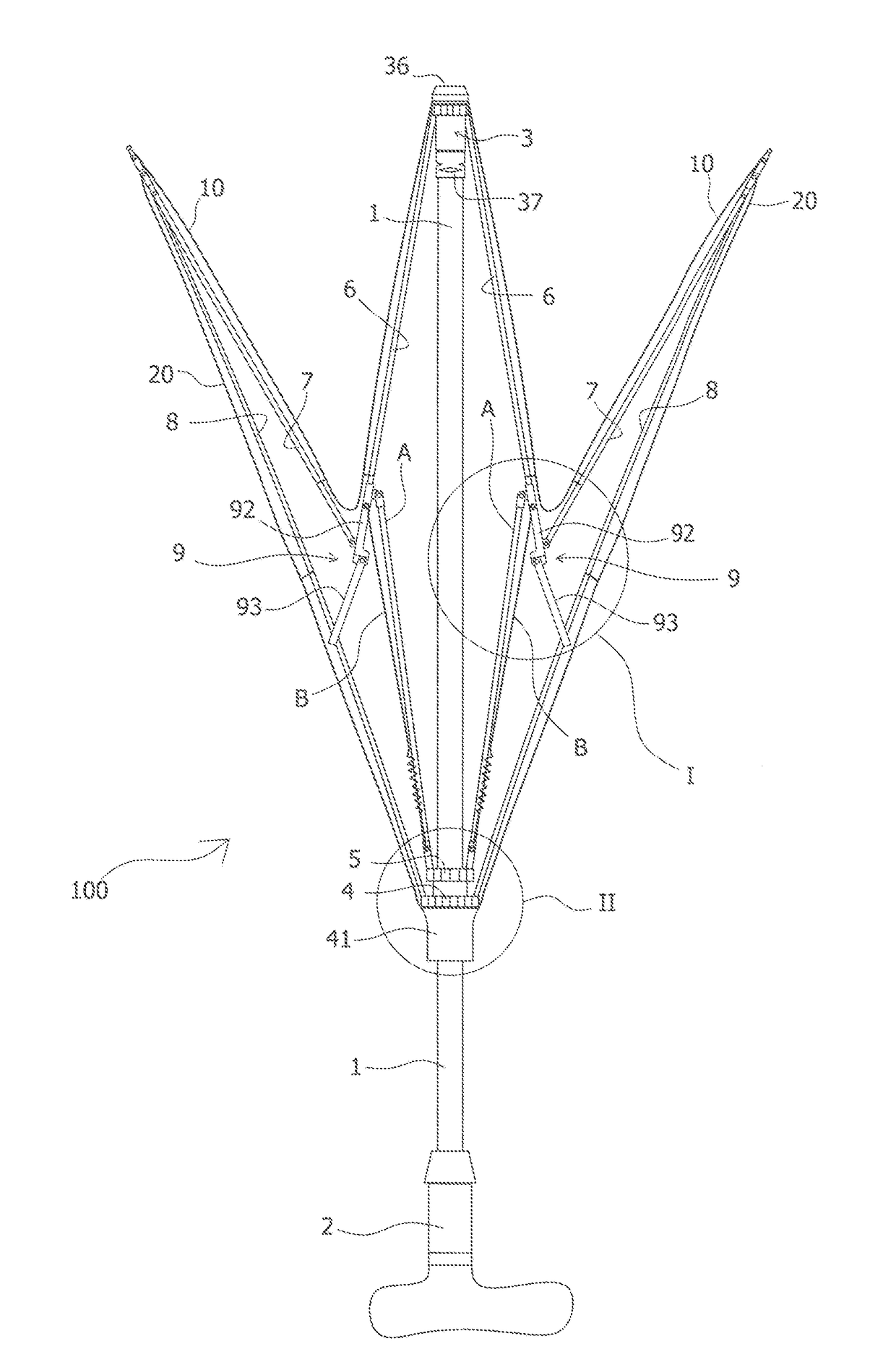
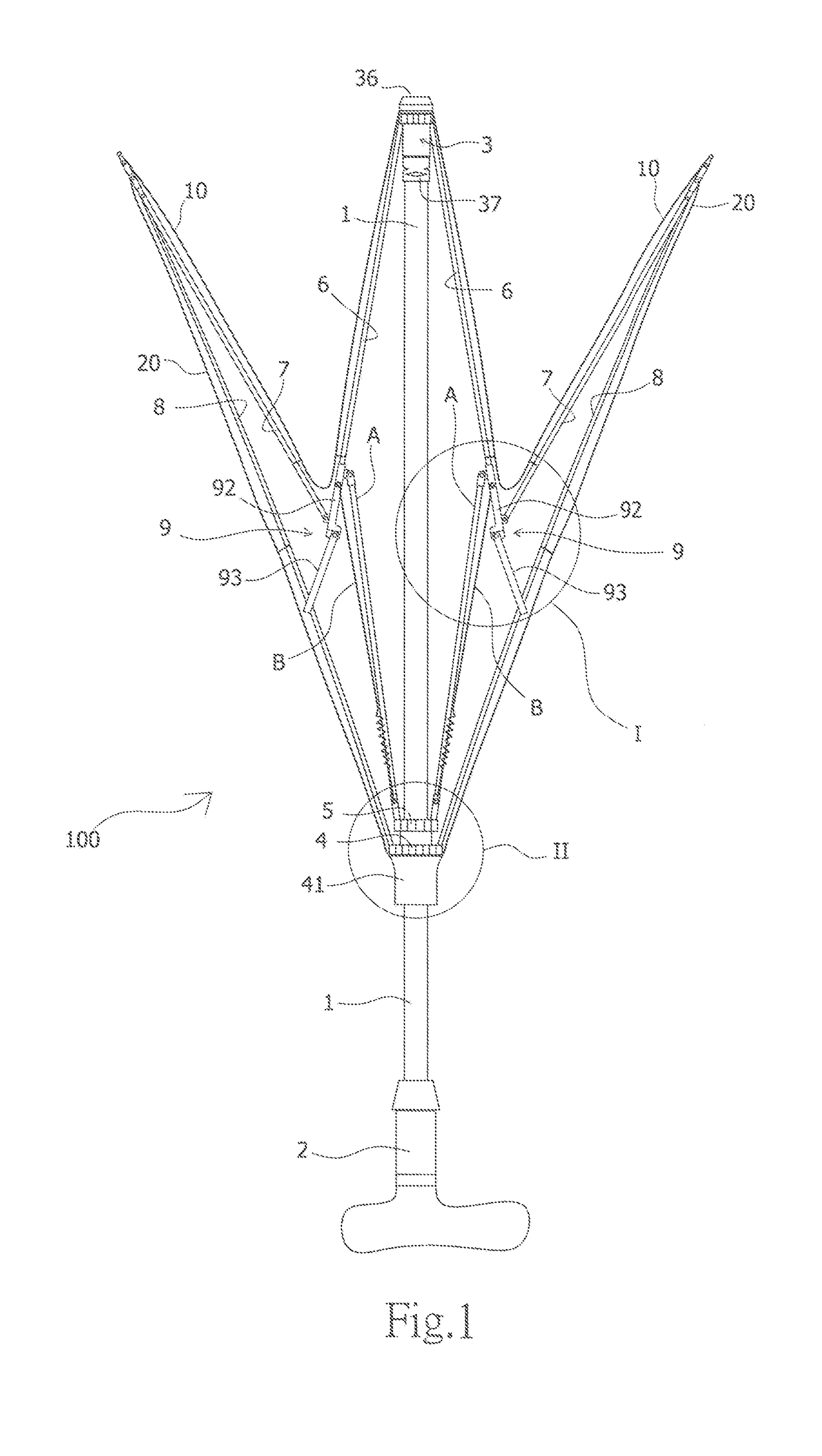
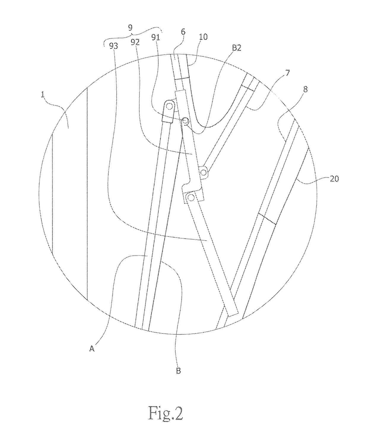
[0041]There are two embodiments of the present invention. First, the first embodiment is described. Referring to FIGS. 1-5, wherein a kind of hand-push rotating umbrella 100 is disclosed, which includes: an umbrella shaft 1; a handle 2 provided at the bottom of the umbrella shaft 1; an upper runner 3 provided at the top of the umbrella shaft 1; a moveable runner 4 provided between the upper runner 3 and handle 2; a middle runner 5 provided at the top of the moveable runner 4; several upper rib supporting rods 6 pin-jointed at the periphery of the upper runner 3; a reversely-folded rib supporting rod 7 pin jointed with one end of the upper rib supporting rods 6; lower rib supporting rods 8 pin-jointed with the reversely-folded rib supporting rod 7 on one end and the moveable runner 4 on the other end; moveable brace rods 9 pin-jointed with the upper rib supporting rods 6 on one end and sleeved on the lower rib supporting rods 8 on the other end; an outer umbrella cloth 10 provided ou...

second embodiment

[0056]Please refer to FIGS. 10 to 12 to introduce the present invention.

[0057]10. A hand-push rotating umbrella, comprising: an umbrella shaft (1), a handle (2) disposed at a bottom of the umbrella shaft (1), an upper runner (3) disposed at a top of the umbrella shaft (1), a moveable runner (4) disposed between the upper runner (3) and handle (2), a middle runner (5) disposed at a top of the moveable runner (4), a plurality of upper rib supporting rods (6) pivotally jointed at a periphery of the upper runner (3), a reversely-folded rib supporting rod (7) pivotally jointed with one end of the upper rib supporting rods (6), lower rib supporting rods (8) having one end thereof pivotally jointed with the reversely-folded rib supporting rod (7) and having another end thereof pivotally jointed with the moveable runner (4), moveable brace rods (9) having one end thereof pivotally jointed with the upper rib supporting rods (6) and having another end thereof sleeved on the lower rib supporti...


PUM


Abstract

A hand-push rotating umbrella comprises extension springs at one side of the supporting ribs where an upward acting force can be produced by means of the pretension force of the extension spring when the moveable runner is pushed up so that the moveable runner and upper rib supporting rods would not fall down affected by gravity, thus a stable umbrella closing state able to be achieved without providing the engagement structure and solving the problems of the existing reversely-folded umbrella produced by only able to stably close the umbrella by using the engagement structure. Moreover, through the collocation application of the upper runner and moveable runner in the present invention, the umbrella canopy would rotate to offset the impact force caused by the wind resistance or collision in the case of strong wind or umbrella rib collision with some foreign object or person, thus able to avoid stabbing and hurting other people and improve the umbrella use safety.

Description

BACKGROUND OF INVENTIONField of the Invention[0001]The present invention relates to a tech field o a reversely folded umbrella.Description of Related Art[0002]Some companies have developed the umbrellas able to be reversely folded and closed, such as the “a kind of automatically out-turned umbrella”, Patent No. CN205337924U announced in the Mainland China. Its advantages, include the simple structure, convenient way of opening, acting force ensuring the umbrella runner's upward going produced through the umbrella runner pulling by the first elastic piece, nice appearance, strong practicability and good safety. However, it is discovered after use that it still has the following problems:[0003]1. The umbrella is opened such that an acting force ensuring; the umbrella runner's upward going is produced through the second mounting groove pulling by the first elastic piece. Therefore, when the automatically out-turned umbrella is in the closed state, the, automatically out-turned umbrella...

Claims


Application Information

Patent Timeline
IPC IPC(8): A45B19/12A45B25/06A45B25/02
CPCA45B19/12A45B25/06A45B25/02A45B2019/004A45B25/22A45B2019/008A45B2200/1081
Inventor DAI, JENHAO
Owner FAN JENNY
Learn More