Vacuum cleaner

a vacuum cleaner and vacuum cleaner technology, applied in the field of vacuum cleaners, can solve the problems of difficult to detect obstacles, and the vacuum cleaner cannot receive infrared rays properly, and achieve the effect of improving obstacle detection precision

Active Publication Date: 2018-10-18
TOSHIBA LIFESTYLE PROD & SERVICES CORP
View PDF0 Cites 10 Cited by
  • Summary
  • Abstract
  • Description
  • Claims
  • Application Information

AI Technical Summary

Benefits of technology

[0008]An object of the invention is to provide a vacuu

Problems solved by technology

However, for example, with the use of an ultrasonic sensor, presence of a soft curtain, thin cords, or the like in a traveling direction hinders ultrasonic waves from being properly reflected, making it difficult to detect these objects as obstacles.
Also, with the use of an infrared sensor as an example, when a black object, a thin cord, or the like is present as a detection object, it is impossible for the vacuum cleaner to properly re

Method used


Image

  • Vacuum cleaner
  • Vacuum cleaner
  • Vacuum cleaner

Examples


first embodiment

[0023]Hereinbelow, a first embodiment will be described in terms of its constitution with reference to the accompanying drawings.

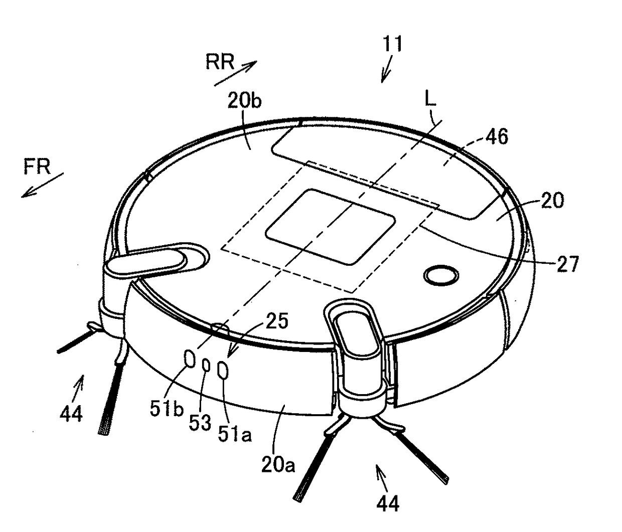
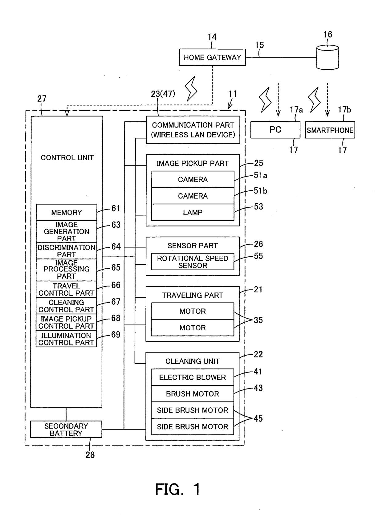
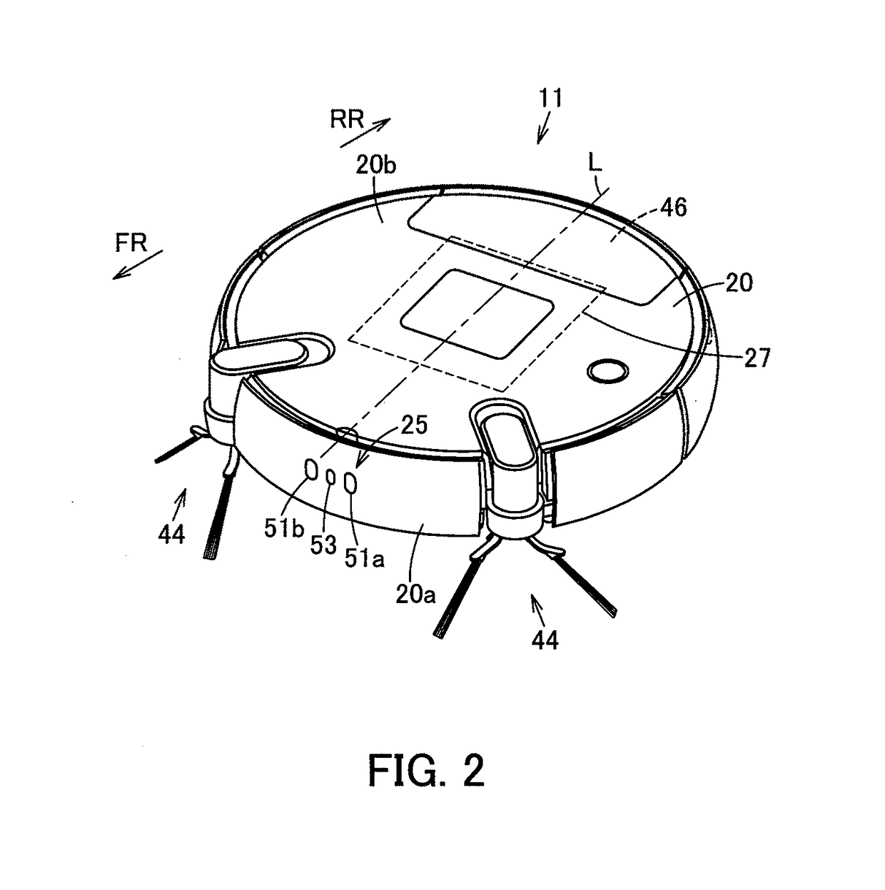
[0024]In FIG. 1 to FIG. 4, reference sign 11 denotes a vacuum cleaner. This vacuum cleaner 11 constitutes a vacuum cleaner device (vacuum cleaner system) in combination with a charging device (charging stand) 12 (FIG. 4) as a station device serving as abase station for charging of the vacuum cleaner 11. Then, the vacuum cleaner 11, in this embodiment, is a so-called self-propelled robot cleaner (cleaning robot) which cleans a floor surface that is a cleaning-object surface as a traveling surface while autonomously traveling (self-propelled to travel) on the floor surface, the vacuum cleaner being enabled to perform wired or wireless communication with a general-purpose server 16 as data storage means (a data storage part) or a general-purpose external device 17 as display means (a display part) via an (external) network 15 such as the Internet, for example...

second embodiment

[0072]In addition, in the second embodiment described above, in the case where the discrimination part 64 re-discriminates whether or not the object is an obstacle while traveling at slower traveling speed after discriminating that the object is an obstacle, the first speed and the second speed have been set. However, the same processing for the discrimination with regard to whether or not the object is an obstacle may be repeated three times or more while traveling at three different levels or more of reduced traveling speed. In this case, it is preferable that the specified set distance be set smaller (the image range of the distance image be set wider) in the case of the traveling speed being lower.

[0073]Also, upon discriminating that the object is an obstacle, the discrimination part 64 can, instead of traveling at lower speed, also re-discriminate whether or not the object is an obstacle after, for example, the vacuum cleaner 11 (main casing 20) is slightly turned by a specifie...

third embodiment

[0076]Next, the third embodiment will be described referring to FIG. 12. In addition, with regard to the same constitution and action as the embodiments described above, respectively the same reference sign is assigned and the description thereof is omitted.

[0077]The third embodiment includes a beam irradiation part 73 as light emitting means (a light emitting part) different from the lamp 53, disposed between the cameras 51a, 51b in the embodiments described above.

[0078]The beam irradiation part 73 with a light-emitting element, for example, an LED or a semiconductor laser is configured to irradiate a light beam B such as visible light or infrared ray forward in the traveling direction of the main casing 20. The beam irradiation part 73 is disposed at the intermediate position between the cameras 51a, 51b, that is, at the position on the center line L in the side surface portion 20a of the main casing 20. That is, the beam irradiation part 73 is distanced generally equally from the...


PUM


Abstract

A vacuum cleaner having improved obstacle detection precision. The vacuum cleaner includes a main casing, driving wheels, control unit, cameras, an image generation part, and a discrimination part. The driving wheels enable the main casing to travel. The control unit controls drive of the driving wheels to make the main casing autonomously travel. The cameras are disposed apart from each other in the main casing to pick up images on a traveling-direction side of the main casing. The image generation part generates a distance image of an object positioned on the traveling-direction side based on the images picked up by the cameras. The discrimination part discriminates whether or not the picked-up object is an obstacle based on the distance image generated by the image generation part.

Description

TECHNICAL FIELD[0001]Embodiments described herein relate generally to a vacuum cleaner including a plurality of image pickup means for picking up images on a traveling-direction side of a main casing.BACKGROUND ART[0002]Conventionally, there has been known a so-called autonomous-traveling type vacuum cleaner (cleaning robot) which cleans a floor surface as a cleaning-object surface while autonomously traveling on the floor surface.[0003]Such a vacuum cleaner is required to avoid obstacles during its traveling. For this reason, the vacuum cleaner uses sensors, such as ultrasonic sensors and infrared sensors, for detection of obstacles that obstruct traveling. However, for example, with the use of an ultrasonic sensor, presence of a soft curtain, thin cords, or the like in a traveling direction hinders ultrasonic waves from being properly reflected, making it difficult to detect these objects as obstacles. Also, with the use of an infrared sensor as an example, when a black object, a ...

Claims


Application Information

Patent Timeline
IPC IPC(8): A47L9/28G01C3/06A47L9/04G05D1/02
CPCA47L9/28G01C3/06A47L9/0411A47L9/0472G05D1/0246G05D2201/0215A47L2201/04A47L2201/06G05D1/0251G06V20/20G05D1/0214A47L9/2805A47L9/2852
Inventor IZAWA, HIROKAZUMARUTANI, YUUKIWATANABE, KOTAFURUTA, KAZUHIRO
Owner TOSHIBA LIFESTYLE PROD & SERVICES CORP
Why Eureka
Try Eureka