Submerged wave energy converter for deep water operations

a technology of energy converter and deep water, applied in the direction of buoyancy control, mechanical equipment, machines/engines, etc., can solve the problems of slow utilization of ocean energy, few existing systems are capable of providing electricity to established power grids, and limited success in harvesting wave energy for electrical energy conversion

Active Publication Date: 2018-10-25
RGT UNIV OF CALIFORNIA
View PDF17 Cites 8 Cited by
  • Summary
  • Abstract
  • Description
  • Claims
  • Application Information

AI Technical Summary

Problems solved by technology

However, successful harvesting of energy from waves for conversion into electrical energy has been generally limited to small scale applications, and few existing systems are capable of providing electricity to established power grids.
One significant reason for the slow utilization of the available energy from the oceans is the damage and destruction that can occur to generating devices from exposure to wave energy from storms, rogue waves and exposure to a high salt marine environment.
Many conventional wave energy converters extract power from the surface of the ocean and must be engineered to survive the power of the harshest ocean storms, which increases the design complexity as well as capital costs.
In addition to being unable to withstand rough weather, the performance of many generating devices will drop significantly during rough weather.
Irregular wave behavior during storms or areas without a consistent flow of powerful waves results in power generation that is unpredictable and erratic and therefore unsuitable as a source for existing power grids.
Other surface wave energy converters produce highly distorted power due to the reciprocal motion induced by the ocean waves.
Wave energy converters may also be location limited.
Surf

Method used


Image

  • Submerged wave energy converter for deep water operations
  • Submerged wave energy converter for deep water operations
  • Submerged wave energy converter for deep water operations

Examples


Embodiment Construction

[0033]In the following description, numerous details are set forth to provide a more thorough explanation of the present invention. It will be apparent, however, to one skilled in the art, that the present invention may be practiced without these specific details. In other instances, well-known structures and devices are shown in block diagram form, rather than in detail, in order to avoid obscuring the present invention.

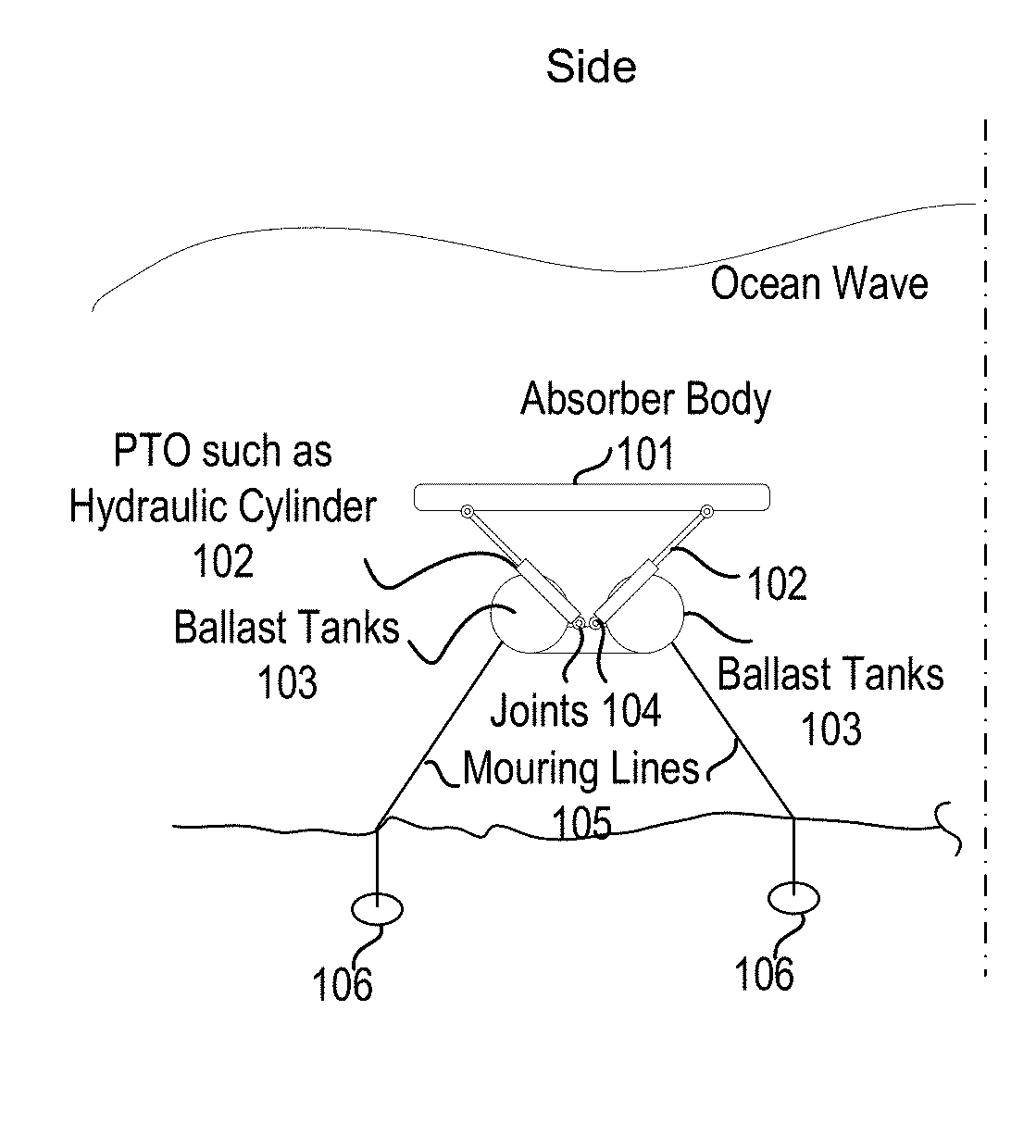
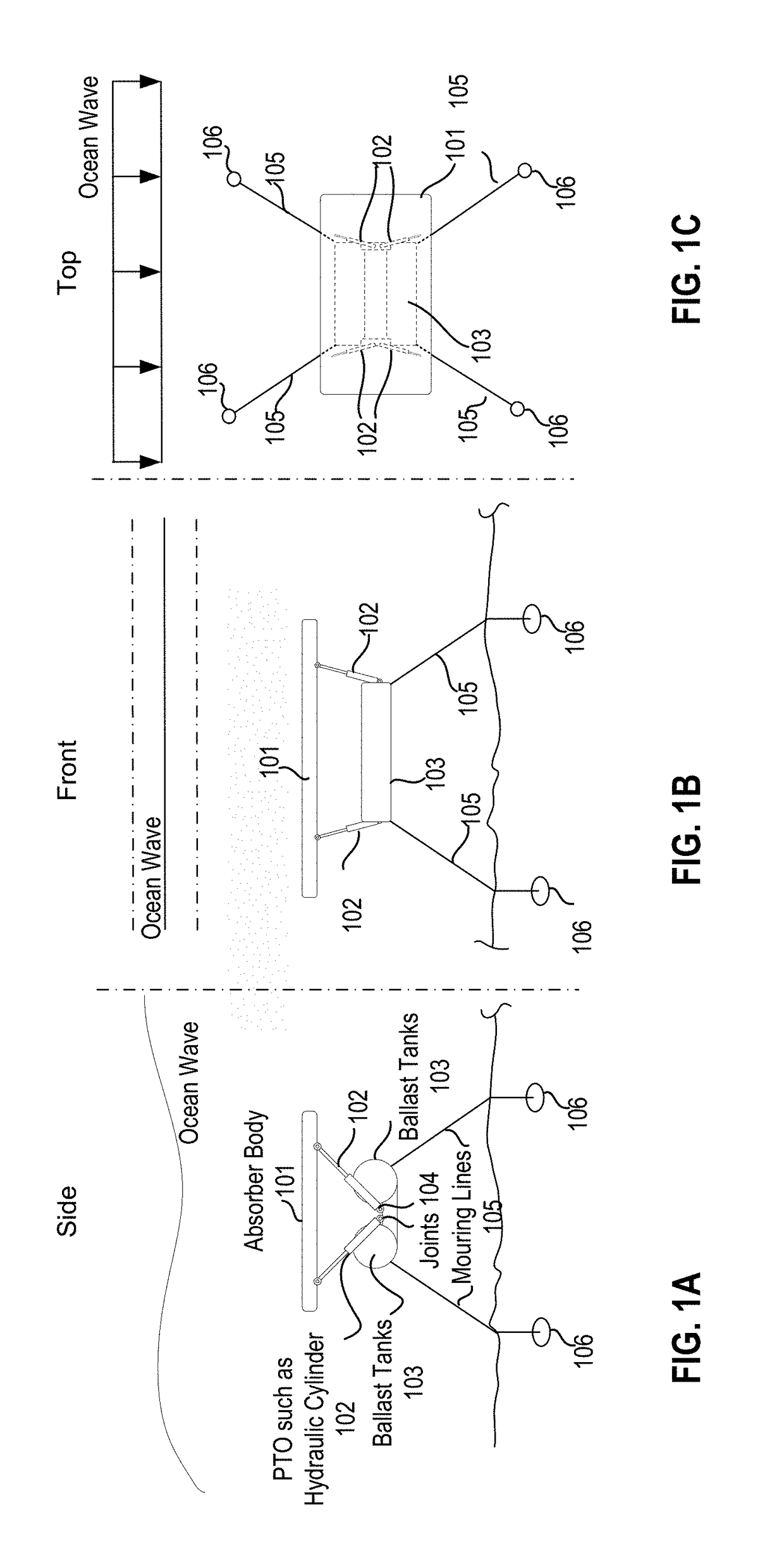
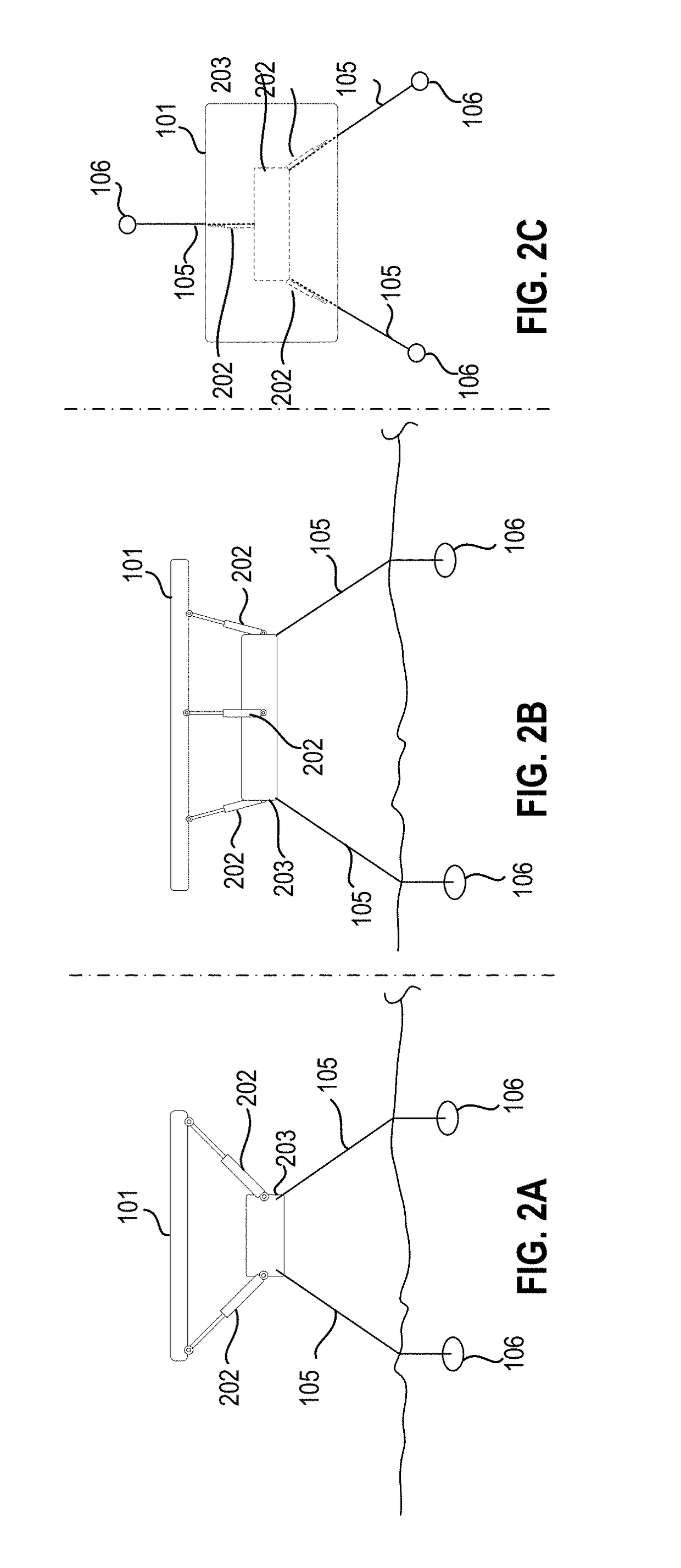
[0034]A system and method for converting wave energy of ocean waves to a motive force derived from pressure differentials created by the system's interaction with ocean water are described. In one embodiment, the system comprises at least one submersible wave energy harvesting body, at least one power take-off unit, at least one restoring force mechanism, and a reaction mechanism providing force acting on the absorber body for energy extraction. In one embodiment, the body includes a system for managing structural loads to maintain energy extraction at a high, and p...


PUM


Abstract

A submergible wave energy converter and method for using the same are described. Such a wave energy converter may be used for deep water operations. In one embodiment, the wave energy converter apparatus comprises an absorber having a body with an upper surface and a bottom surface and at least one power take-off (PTO) unit coupled to the absorber and configured to displace movement of the absorber body relative to a reference, where the power take-off unit is operable to perform motion energy conversion based on displacement of the absorber body relative to the reference in response to wave excitation, and where the power take-off unit is operable to return the absorber body from a displaced position to a predefined equilibrium position and to provide a force acting on the absorber body for energy extraction.

Description

PRIORITY[0001]The present patent claims priority to and incorporates by reference the corresponding provisional patent application Ser. No. 62 / 489,386, titled, “Submerged Wave Energy Converter for Deep Water Operations,” filed on Apr. 24, 2017.STATEMENT REGARDING FEDERALLY SPONSORED RESEARCH OR DEVELOPMENT[0002]This invention was made with Government support under DE-AC02-05CH11231, awarded by the Department of Energy. The Government has certain rights in the invention.NOTICE OF MATERIAL SUBJECT TO COPYRIGHT PROTECTION[0003]A portion of the material in this patent document is subject to copyright protection under the copyright laws of the United States and of other countries. The owner of the copyright rights has no objection to the facsimile reproduction by anyone of the patent document or the patent disclosure, as it appears in the United States Patent and Trademark Office publicly available file or records, but otherwise reserves all copyright rights whatsoever. The copyright own...

Claims


Application Information

Patent Timeline
IPC IPC(8): F03B13/10F03B13/18
CPCF03B13/10F03B13/187F03B13/186F03B13/148F05B2250/22F05B2250/72F05B2260/406F05B2270/18Y02E10/20Y02E10/30F03B13/20F05B2240/97
Inventor LEHMANN, MARCUSALAM, MOHAMMAD-REZABOERNER, THOMASKOJIMOTO, NIGELMURRAY, BRYAN
Owner RGT UNIV OF CALIFORNIA
Why Eureka
Try Eureka