Rack bar and rack bar manufacturing method

Inactive Publication Date: 2018-10-25
NETUREN CO LTD
View PDF10 Cites 9 Cited by
  • Summary
  • Abstract
  • Description
  • Claims
  • Application Information

AI Technical Summary

Benefits of technology

[0007]According to another illustrative aspect of the present invention, a method for manufacturing the rack bar is provided. The method includes applying the adhesive to at least one of the inner peripheral surface of the first joining portion of the joint member and the outer peripheral surface of an end portion of the first bar member, and fitting the end portion of the first bar member into the first joining portion, applying the adhesive

Problems solved by technology

However, the materials of the first bar member, the second bar member and the joint member are basicall

Method used


Image

  • Rack bar and rack bar manufacturing method
  • Rack bar and rack bar manufacturing method
  • Rack bar and rack bar manufacturing method

Examples


Embodiment Construction

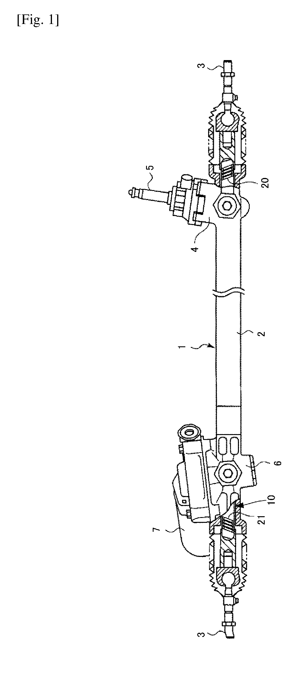
[0013]FIG. 1 illustrates a steering apparatus 1 according to an embodiment of the present invention.

[0014]The steering apparatus 1 has a rack housing 2 and a rack bar 10 housed in the rack housing 2 so as to be slidable in an axial direction.

[0015]To each end portion of the rack bar 10, a tie rod 3 is coupled through a joint, and by a movement of the rack bar 10, vehicle wheels are turned through the tie rod 3 and a steering mechanism to which the tie rod 3 is coupled.

[0016]At one axial end portion of the rack housing 2, a steering gear box 4 is provided. Inside the steering gear box 4, a steering pinion (not shown) formed on an input shaft 5 coupled to the steering shaft is provided. At the other axial end portion of the rack housing 2, an assist gear box 6 is provided. Inside the assist gear box 6, an assist pinion (not shown) driven by a motor 7 of an assisting mechanism is provided.

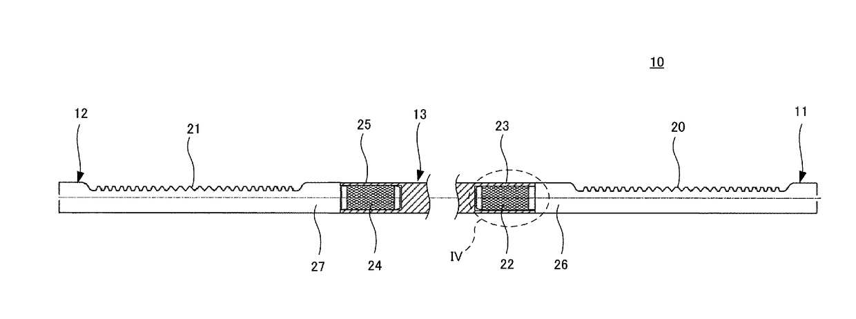
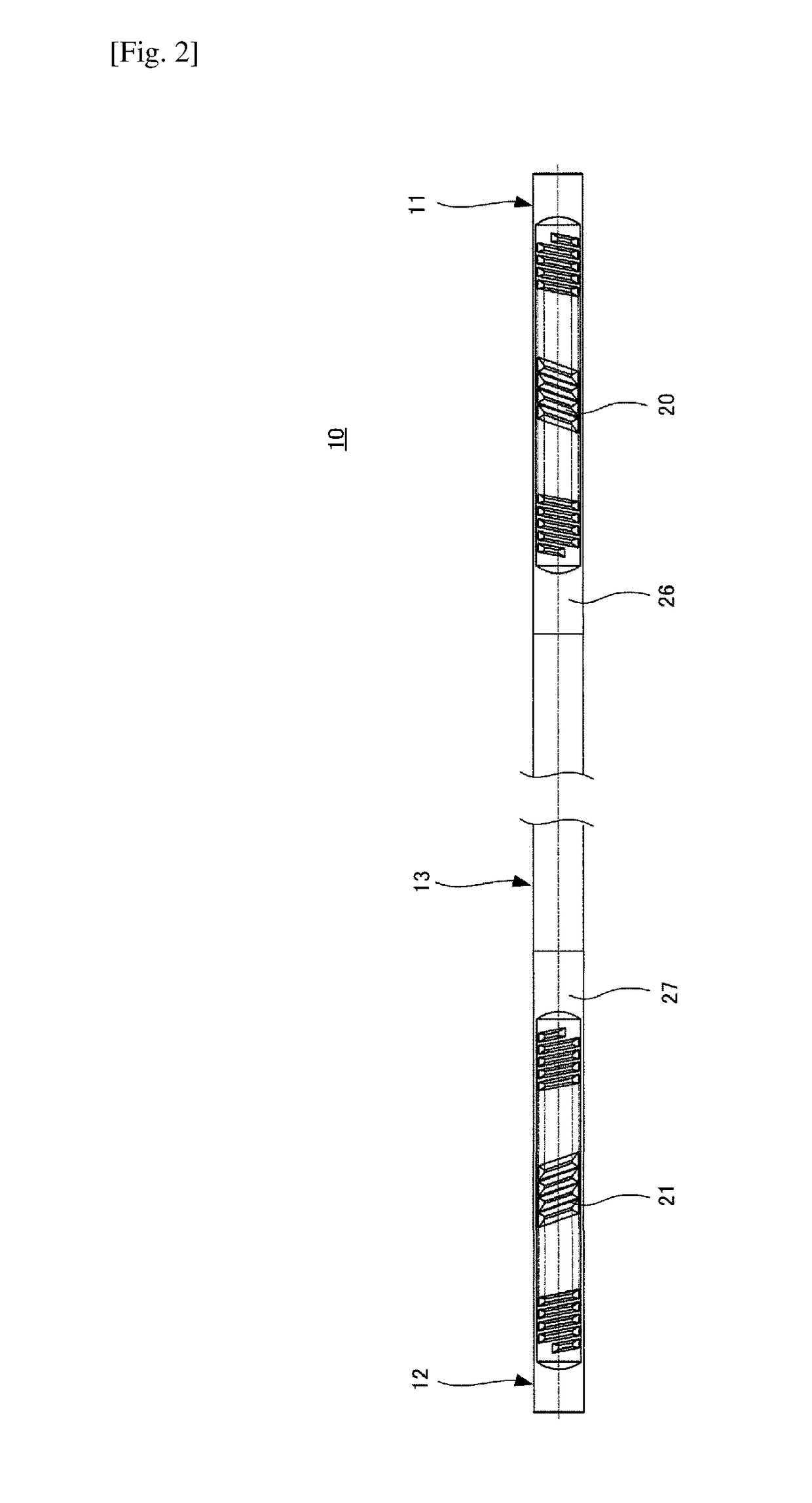
[0017]The rack bar 10 has a first toothed portion 20 and a second toothed portion 21. The first to...


PUM

PropertyMeasurementUnit
Shapeaaaaaaaaaa

Abstract

A rack bar (10) includes a first bar member (11) having a first toothed portion (20), a second bar member (12) having a second toothed portion (21), and a joint member coaxially coupling the first and second bar members. The joint member (13) has a first joining portion (23) and a second joining portion (25) that are provided coaxially with each other. Each of the first and second joining portions has a hollow cylindrical shape. An inner peripheral surface of the first joining portion and an outer peripheral surface of an end portion (22) of the first bar member are joined to each other with an adhesive. An inner peripheral surface of the second joining portion and an outer peripheral surface of an end portion (24) of the second bar member are joined to each other with an adhesive.

Description

TECHNICAL FIELD[0001]The present invention relates to a rack bar and a rack bar manufacturing method.BACKGROUND ART[0002]Some vehicle steering apparatuses of an automobile and the like have a dual-pinion rack bar having rack toothed portions at two locations, one of the toothed portion meshing with a steering pinion of a steering shaft and the other toothed portion meshing with an assist pinion of an assisting mechanism. Depending on a positional relationship between the steering shaft and the assisting mechanism in the vehicle, the toothed portions at two locations on the dual-pinion rack bar may be designed to have a angular difference around an axis of the rack bar.[0003]According to a related art method for manufacturing such a dual-pinion rack bar, with the aim of improving the accuracy of the angular difference between the toothed portions at two locations, a first bar member having a first toothed portion and a second bar member having a second toothed portion are coaxially a...

Claims


Application Information

Patent Timeline
IPC IPC(8): F16H55/26F16H55/06B62D3/12B29C65/48B29C65/00
CPCF16H55/26F16H55/06B62D3/126B29C65/48B29C66/721B29C66/5221B29K2307/04B29L2031/30B21K1/76B62D3/12
Inventor INAGAKI, KOICHIMATSUMOTO, WATARU
Owner NETUREN CO LTD
Why Eureka
Try Eureka