
Vise stop arrangement

a technology of vise stop and abutment, which is applied in the direction of manufacturing tools, and the like, can solve the problems of affecting the integrity of the key, the small size of the key, and the potential lack of durability, and achieve the effect of facilitating access

Active Publication Date: 2018-11-01
CONCEPTS TO SOLUTIONS LLC
View PDF5 Cites 5 Cited by
  • Summary
  • Abstract
  • Description
  • Claims
  • Application Information

AI Technical Summary

Benefits of technology

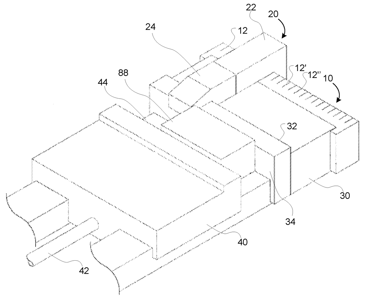
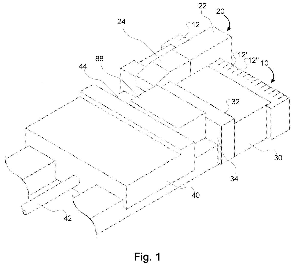
The patent describes a vise stop that can be used to hold a workpiece in place during milling. The vise stop has two pieces that are connected to each other using a threaded fastener. The two pieces can interlock using a protrusion and channel arrangement. The vise stop can also be a single piece that can be milled to access parts of the workpiece that would be blocked if the vise stop was in place. This makes it easier to prepare the workpiece for milling.

Problems solved by technology

However, the key is very small and potentially lacks durability.
The integrity of the key is further compromised by the channel disposed through its center which is used for the attachment of the key to the top of the vise jaw, the channel representing a potential point of failure of the key when the workpiece is rested against it and subjected to force during milling operations.

Method used


Image

  • Vise stop arrangement
  • Vise stop arrangement
  • Vise stop arrangement

Examples


Embodiment Construction

[0021]Specific details of certain embodiments of the invention are set forth in the following description and in the figures to provide a thorough understanding of such embodiments. The present invention may have additional embodiments, may be practiced without one or more of the details described for any particular described embodiment, or may have any detail described for one particular embodiment practiced with any other detail described for another embodiment.

[0022]Importantly, a grouping of inventive aspects in any particular “embodiment” within this detailed description, and / or a grouping of limitations in the claims presented herein, is not intended to be a limiting disclosure of those particular aspects and / or limitations to that particular embodiment and / or claim. The inventive entity presenting this disclosure fully intends that any disclosed aspect of any embodiment in the detailed description and / or any claim limitation ever presented relative to the instant disclosure a...


PUM


Abstract

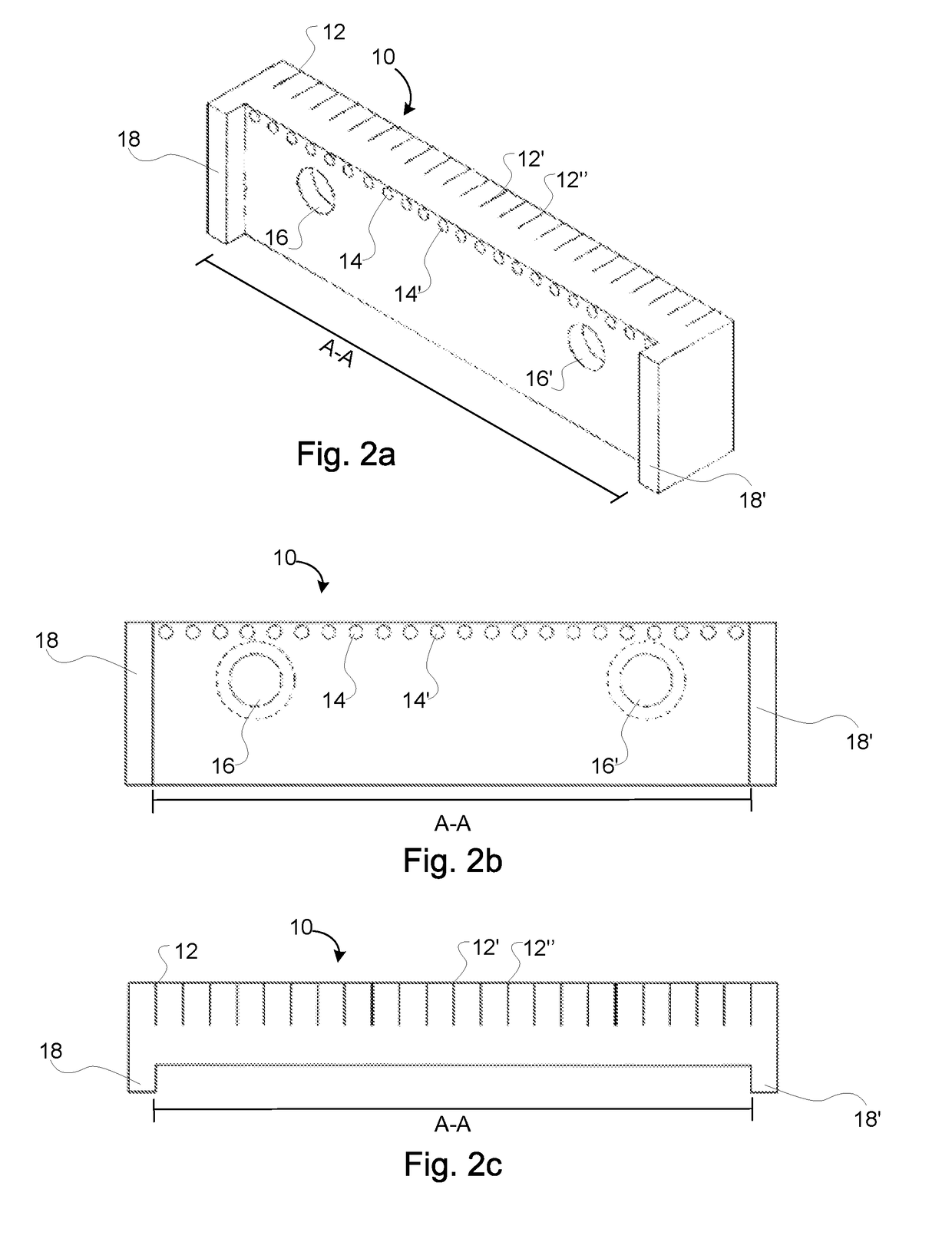
An arrangement of a carrier plate and vise stop which provide an abutment against which a workpiece rests laterally when being milled. The carrier plate affixes to a rear portion of a fixed jaw of a milling machine, the carrier plate having a forward recess for receiving the rear portion of the fixed jaw which nestles into the recess as the recess is dimensioned for receiving at least three sides of the fixed jaw. The carrier plate includes a plurality of locator chambers sized for receiving dowel pins of a vise stop, whereby adjacent locator chambers are spaced at a constant distance apart from one another. The interlocking of the dowels of the vise stop and the carrier plate may occur at varied lateral locations between the sides of the milling machine. A nose of the vise stop extends into the work area of the milling machine, providing the abutment.

Description

PRIORITY CLAIM[0001]The present application is related to and / or claims the benefits of the earliest effective priority date and / or the earliest effective filing date of the below-referenced applications, each of which is hereby incorporated by reference in its entirety, to the extent such subject matter is not inconsistent herewith, as if fully set forth herein:[0002](1) this application constitutes a non-provisional of U.S. Provisional Patent Application No. 62 / 523,088, entitled WORK PIECE POSITIONING ASSEMBLY AND HEMBACK VISE, naming Edward Mack as the inventor, filed Jun. 21, 2017, with attorney docket no. 72477.001, which is currently co-pending or is an application of which a currently co-pending application is entitled to the benefit of the filing date.FIELD OF THE INVENTION[0003]This invention relates generally to work holders, particularly of the work-stop abutment type, and, more specifically, to a vise stop arrangement.BACKGROUND OF THE INVENTION[0004]When milling a workp...

Claims


Application Information

Patent Timeline
IPC IPC(8): B25B1/24
CPCB25B1/2468
Inventor MACK, EDWARD
Owner CONCEPTS TO SOLUTIONS LLC
Learn More