Control system, vehicle and method

a control system and vehicle technology, applied in the direction of tyre parts, tyre tread bands/patterns, tyre measurements, etc., can solve the problems of accelerating tire wear, affecting the performance of these safety features, and increasing difficulty in traversing a terrain

Inactive Publication Date: 2018-11-01
JAGUAR LAND ROVER LTD
View PDF4 Cites 9 Cited by
  • Summary
  • Abstract
  • Description
  • Claims
  • Application Information

AI Technical Summary

Benefits of technology

[0009]It is to be understood that embodiments of the present invention have the advantage that a user is not required to remember to reset the cumulative tire wear indicator value to the predetermined datum value when a tire has been changed. Rather, the control system is configured automatically to determine that a tire has been changed. The control system may require user confirmation of a tire change bore the indicator value is set to the predetermined datum value, but the user is not required to initiate the process.
[0037]In some embodiments, and in particular, embodiments where a tire pressure monitoring device is permanently attached to a tire, the CTIS controller may be provided with a signal indicative of a usage history of the tire pressure monitoring device based on data stored in a memory of the tire pressure monitoring device. For example in some embodiments the tire pressure monitoring device may be configured to store data indicative of the number of rotations the tire pressure monitoring device has experienced, the amount of time since it was manufactured, the amount of time the sensor has been exposed to a pressure exceeding a predetermined pressure or any other suitable data enabling the CTIS controller to determine whether the tire is likely to have been subject to not insignificant prior use.

Problems solved by technology

It is to be understood that inadvertent selection of an on-road mode such as normal run mode 201NR when driving off-road may be inappropriate and result in increased difficulty traversing a terrain.
The performance of these safety features can be affected by tire pressure.
It is to be understood that operation of vehicles at lower tire pressures than those used for on-road driving, such as at tire pressures suitable for off-road driving on relatively slippery terrain, can result in accelerated tire wear.

Method used


Image

  • Control system, vehicle and method
  • Control system, vehicle and method
  • Control system, vehicle and method

Examples


Embodiment Construction

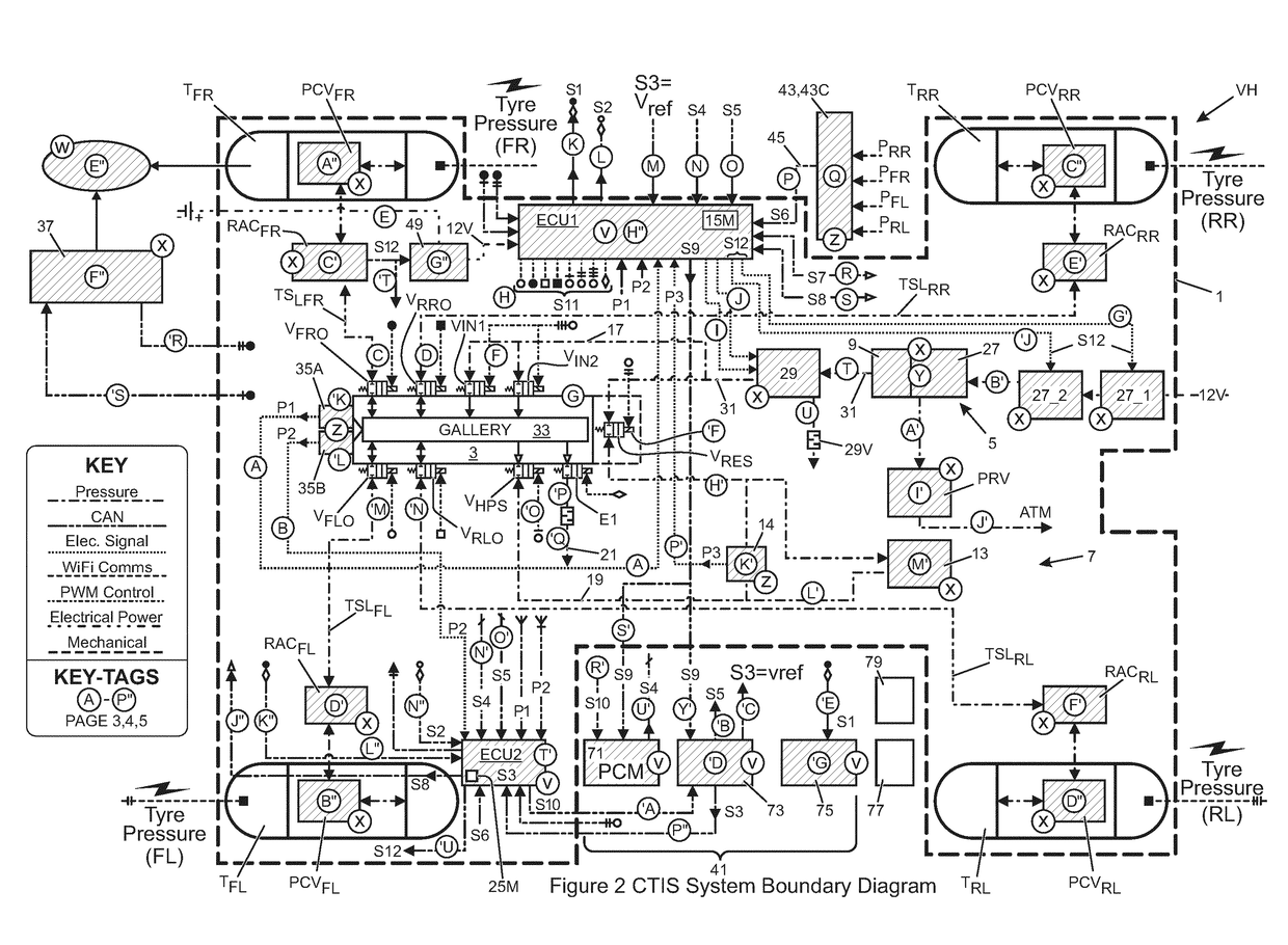
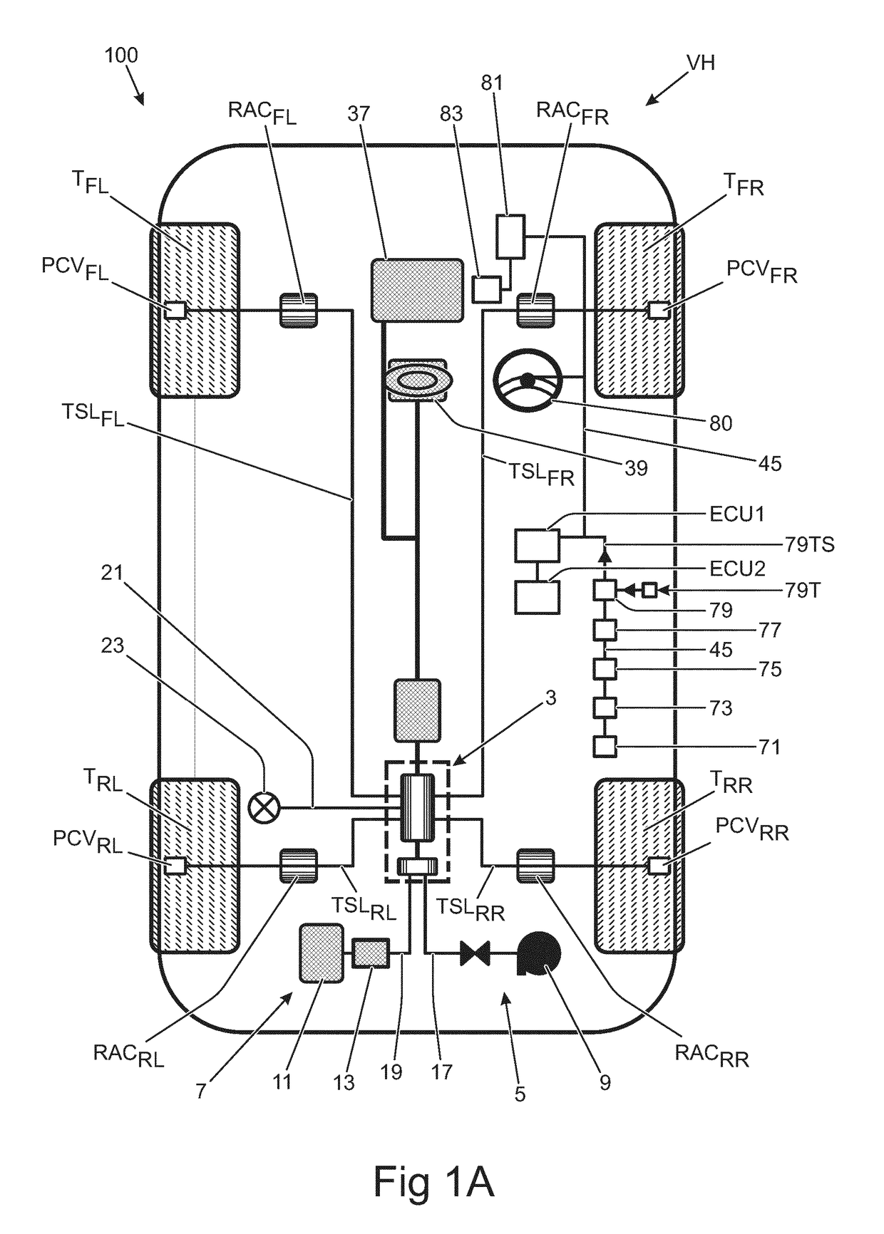
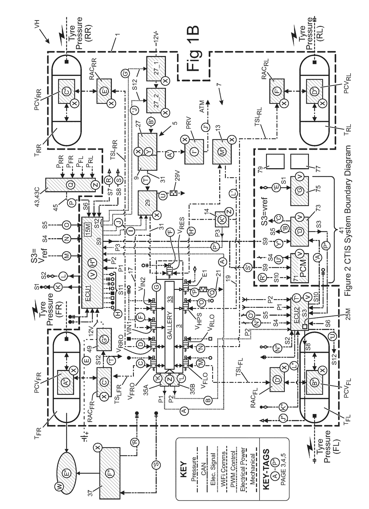
[0065]In the following description and in the drawings, reference letters are used to collectively or un-specifically identify equivalent or essentially equivalent components. Where necessary, a specific component in a collection of equivalent or essentially equivalent components may be identified by suffixing a reference letter in subscript format.

[0066]It is to be understood that by the term ‘key off’ (power mode 0) herein is meant the assumption by the vehicle or portion thereof of a configuration requiring the presence of a security device such as a key, key fob or other security device in order for the vehicle to be restarted at ‘key on’. For example if the vehicle has an internal combustion engine the engine is shut down at key off in a manner that requires a direct driver intervention other than release of a brake or actuation of an accelerator control in order to restart the engine, e.g. a key turn, or the press of a start button when a security device is in the proximity of...


PUM


Abstract

A control system for a motor vehicle includes a central tire inflation system (CTIS) electronic controller, the CTIS controller being configured to control the CTIS to cause inflation and deflation of one or more tires, the CTIS controller being configured to receive electronic signals indicative of current vehicle speed and tire pressure, and to generate a cumulative tire wear indicator value indicative of a cumulative amount of wear suffered by a tire at a given moment in time, the CTIS controller being configured to automatically set the cumulative tire wear indicator value to a predetermined datum value in dependence at least in part on a determination by the CTIS controller that a tire has been changed.

Description

TECHNICAL FIELD[0001]The present invention relates to central tire inflation systems (CTIS's) and to a related method.BACKGROUND[0002]Central tire inflation systems (CTIS's) were originally developed for military applications, in particular for military applications concerning off-road military wheeled trucks and trailers. However, CTIS's are nowadays incorporated into non-military vehicles such as specialist construction equipment and some agricultural vehicles.[0003]A CTIS typically comprises a compressed air source located on-board the vehicle and connected to one or more tire. Tire pressure can therefore be adjusted by operating the CTIS. The CTIS delivers compressed air to tire supply lines. In some examples, the supply lines are integrated into the vehicle axles. Various valves are provided in the CTIS to control flow of compressed air.[0004]At least in certain embodiments, the present invention aims to solve, or at least mitigate, at least some problems that can be identified...

Claims


Application Information

Patent Timeline
Patent Type & Authority Applications(United States)
IPC IPC(8): B60C23/00B60C11/24
CPCB60C23/002B60C11/246B60C23/003B60C2019/004B60C23/00354B60C23/00372B60C11/24B60C11/243B60C23/00B60C23/001B60C23/04
Inventor WOODLEY, JONATHANCIOVNICU, ROXANA
Owner JAGUAR LAND ROVER LTD
Why Eureka
Try Eureka