Gas generator
- Summary
- Abstract
- Description
- Claims
- Application Information
AI Technical Summary
Benefits of technology
Problems solved by technology
Method used
Image
Examples
first example
[0133]FIG. 8 shows a table of specifications of the gas generator according to the first example and results of measurement when the gas generator is activated.
[0134]As shown in FIG. 8, the gas generator according to the first example achieves an amount of gas generation of 2.0 [mol] and has a thickness T of the housing decreased to 1.2 [mm]. The gas generator according to the first example has thus a weight reduced to 320 [g].
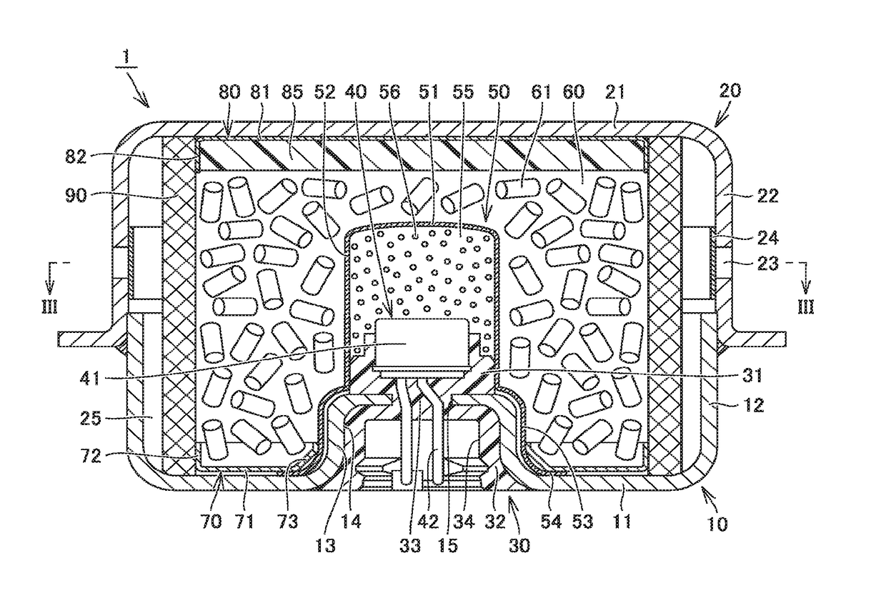
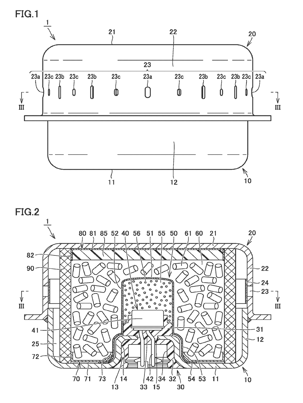
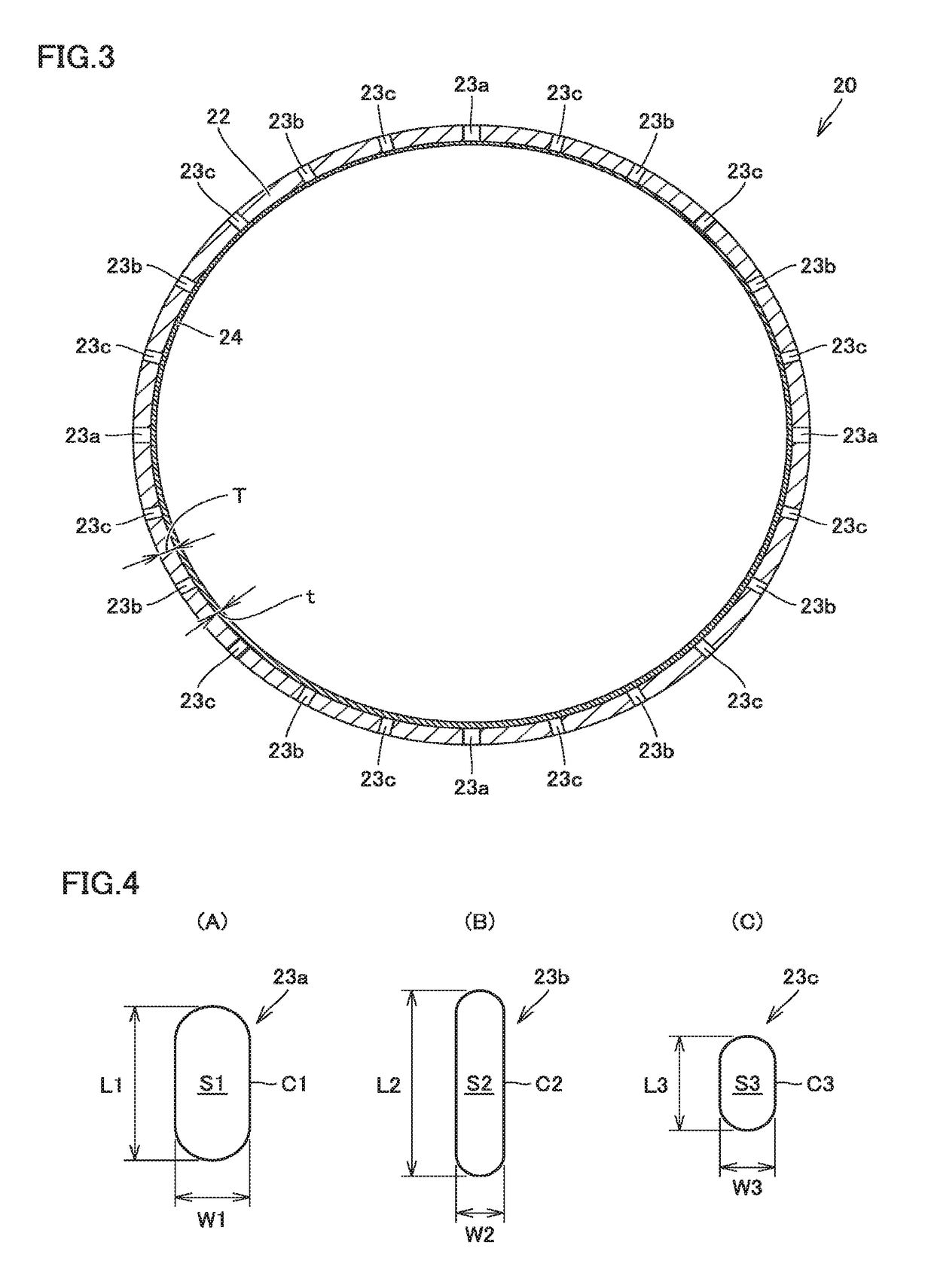
[0135]Opening pressures of a plurality of gas discharge openings are set differently from one another in three levels and total opening area SA of the plurality of gas discharge openings is 115.55 [mm2]. Details of first to third gas discharge openings 23a to 23c set in the three levels and details of the sealing tape are as shown in FIG. 8. In particular, set ratios P1 / P3 and P2 / P3 described previously are set to 0.68 and 0.91, respectively, and ratios Sa1 / SA, Sa2 / SA, and Sa3 / SA described previously are set to 0.26, 0.41, and 0.33, respectively.
[0136]The gas ...
second example
[0137]FIG. 9 shows a table of specifications of the gas generator according to the second example and results of measurement when the gas generator is activated.
[0138]As shown in FIG. 9, the gas generator according to the second example achieves an amount of gas generation of 1.2 [mol] and has a thickness T of the housing decreased to 1.2 [mm]. The gas generator according to the second example has thus a weight reduced to 220 [g].
[0139]Opening pressures of a plurality of gas discharge openings are set differently from one another in three levels and total opening area SA of the plurality of gas discharge openings is 80.64 [mm2]. Details of first to third gas discharge openings 23a to 23c set in the three levels and details of the sealing tape are as shown in FIG. 9. In particular, set ratios P1 / P3 and P2 / P3 described previously are set to 0.63 and 0.83, respectively, and ratios Sa1 / SA, Sa2 / SA, and Sa3 / SA described previously are set to 0.42, 0.28, and 0.29, respectively.
[0140]The ga...
third example
[0141]FIG. 10 shows a table of specifications of the gas generator according to the third example and results of measurement when the gas generator is activated.
[0142]As shown in FIG. 10, the gas generator according to the third example achieves an amount of gas generation of 1.2 [mol] and has a thickness T of the housing decreased to 1.2 [mm]. The gas generator according to the third example has thus a weight reduced to 220 [g].
[0143]Opening pressures of a plurality of gas discharge openings are set differently from one another in three levels and total opening area SA of the plurality of gas discharge openings is 80.47 [mm2]. Details of first to third gas discharge openings 23a to 23c set in the three levels and details of the sealing tape are as shown in FIG. 10. In particular, set ratios P1 / P3 and P2 / P3 described previously are set to 0.60 and 0.81, respectively, and ratios Sa1 / SA, Sa2 / SA, and Sa3 / SA described previously are set to 0.38, 0.33, and 0.29, respectively.
[0144]The ga...
PUM
 Abstract
Description
Claims
Application Information
 - R&D Engineer
- R&D Manager
- IP Professional
- Industry Leading Data Capabilities
- Powerful AI technology
- Patent DNA Extraction
Browse by: Latest US Patents, China's latest patents, Technical Efficacy Thesaurus, Application Domain, Technology Topic.
© 2024 PatSnap. All rights reserved.Legal|Privacy policy|Modern Slavery Act Transparency Statement|Sitemap


