Vertical takeoff and landing airframe

a vertical takeoff and landing and airframe technology, applied in vertical landing/takeoff aircraft, transportation and packaging, floats, etc., can solve the problems of high aspect ratio fixed wings, slow maneuverability, and need for runways or other runouts for takeoff and landing, etc., to achieve large flight envelope, efficient forward flight, and versatile performance

Active Publication Date: 2018-11-01
PTERODYNAMICS INC
View PDF3 Cites 39 Cited by
  • Summary
  • Abstract
  • Description
  • Claims
  • Application Information

AI Technical Summary

Benefits of technology

[0008]The present disclosure generally provides airframes that address the shortcomings of prior attempts and enable efficient forward flight along with vertical takeoff and landing. Generally speaking, the embodiments described herein can achieve such versatile performance by employing a unique configuration of tilting wings and propulsion units that enable a large flight envelope encompassing both hovering and forward flight at a range of speeds.
[0009]The airframes described herein can perform repeated in-flight transformations between a compact and maneuverable hovering or slow speed configuration (e.g., similar to a multirotor drone, helicopter, or other hovering aircraft) and a lifting wing configuration capable of efficient horizontal flight (e.g., similar to a fixed wing aircraft). In the hovering or slow speed configuration, the weight of an aircraft can be substantially supported by the thrust of its propulsion units, which can be coupled to the tilting wings such that they are also tilted to direct their thrust more vertically. In the forward flight configuration, the weight of the aircraft can be substantially supported by the lift generated from the wings and the propulsion thrust can be directed more horizontally. Further, a continuous range of intermediate tilting positions can also be employed to provide varying levels of thrust- or wing-developed lifting force. The airframes disclosed herein provide a unique ability to smoothly and stably transition between these two operating modes in-flight and / or operate indefinitely in an intermediate mode.
[0010]These performance characteristics can, in some embodiments, be achieved by utilizing a folding wing structure that pivots on a slanted axis, i.e., an axis that is oblique to a longitudinal or lateral axis of the aircraft. Such a folding motion can orient a leading edge of each wing in an upward or forward direction, depending on the tilt of the wing. Further, in a tilted configuration the wings can extend along the fuselage of the aircraft to reduce the moment of inertia created by their mass, their aerodynamic impact during hover, as well as space required for storage or ground transport. Further, in some embodiments a portion of the wings folded in this manner can include propulsion units coupled thereto such that thrust can be redirected between a horizontal and a vertical direction as the wings are tilted or folded.

Problems solved by technology

These airframes can have several disadvantages as well, including difficulty maneuvering at slow speeds and the need for runway or other runout for takeoff and landing.
In such configurations, however, high aspect ratio fixed wings can be detrimental.
For example, long fixed wings can be difficult to maneuver during STOL or VTOL operation due to a large moment of inertia created by their mass being extended away from a center of gravity of the aircraft.
Further, there can be significant aerodynamic drag from moving a wing in a manner that presents its largest surface area as a leading edge.
While such designs can aid in alleviating the above-described aerodynamic losses from moving a wing in a direction substantially normal to its intended angle of attack, they can still be difficult to maneuver due to the large moment of inertia of the extended wings.
Prior configurations of both tilt-engine and tilt-wing airframes that can achieve STOL or VTOL operation also suffer from instability during transition from takeoff or landing configurations to forward flight configurations.
Accordingly, such aircraft often exhibit bimodal operation envelopes and cannot stably or indefinitely operate at any speed between the takeoff or landing realm and the high-speed forward flight realm.
A further disadvantage of high aspect ratio fixed wing airframes is the need for substantial storage space at rest and substantial clearance during ground transport.
These mechanisms, however, are often tailored to ground storage or transport and are not operable during flight to enable, for example, vertical takeoff and landing, etc.

Method used


Image

  • Vertical takeoff and landing airframe
  • Vertical takeoff and landing airframe
  • Vertical takeoff and landing airframe

Examples


Embodiment Construction

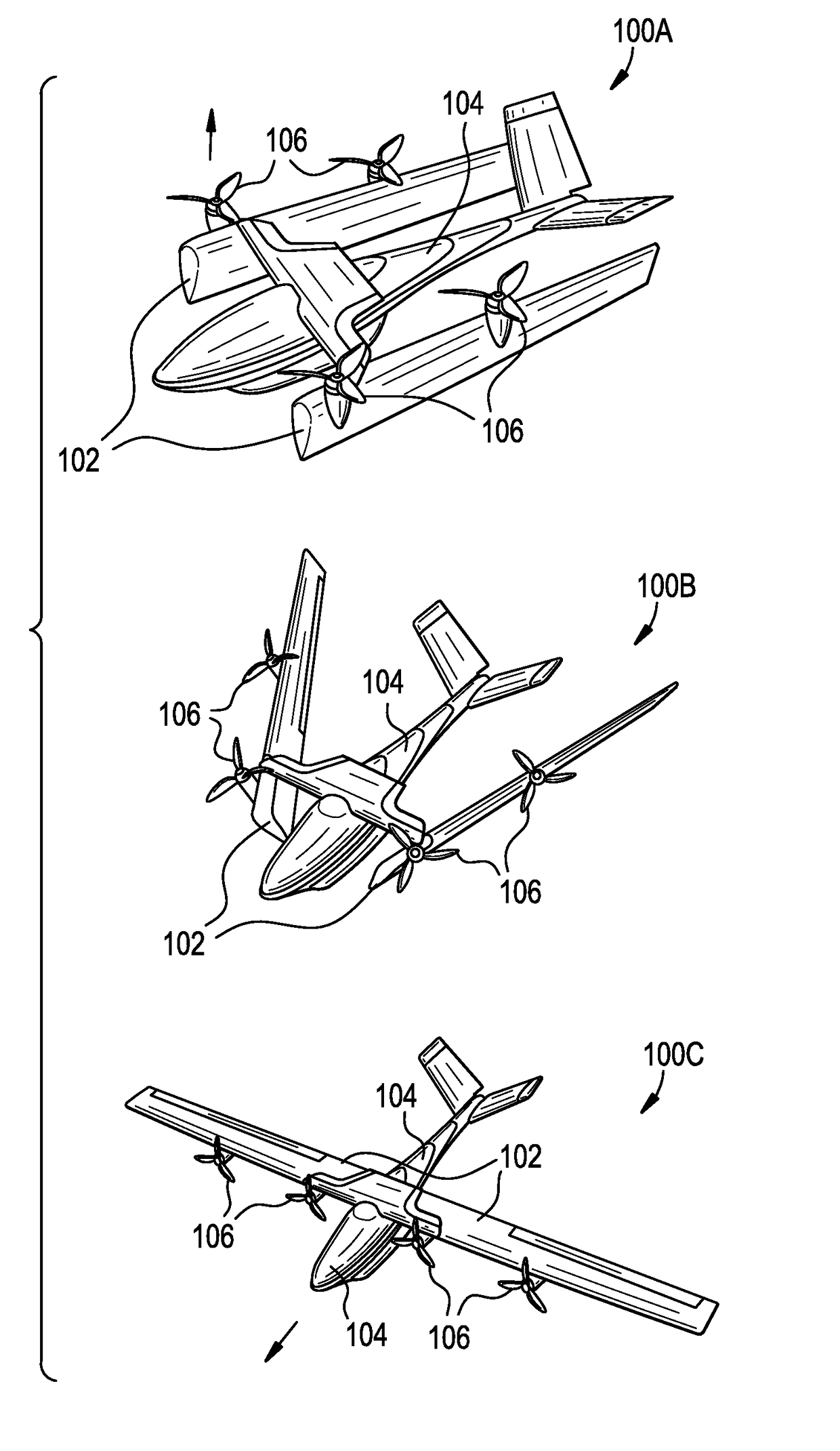
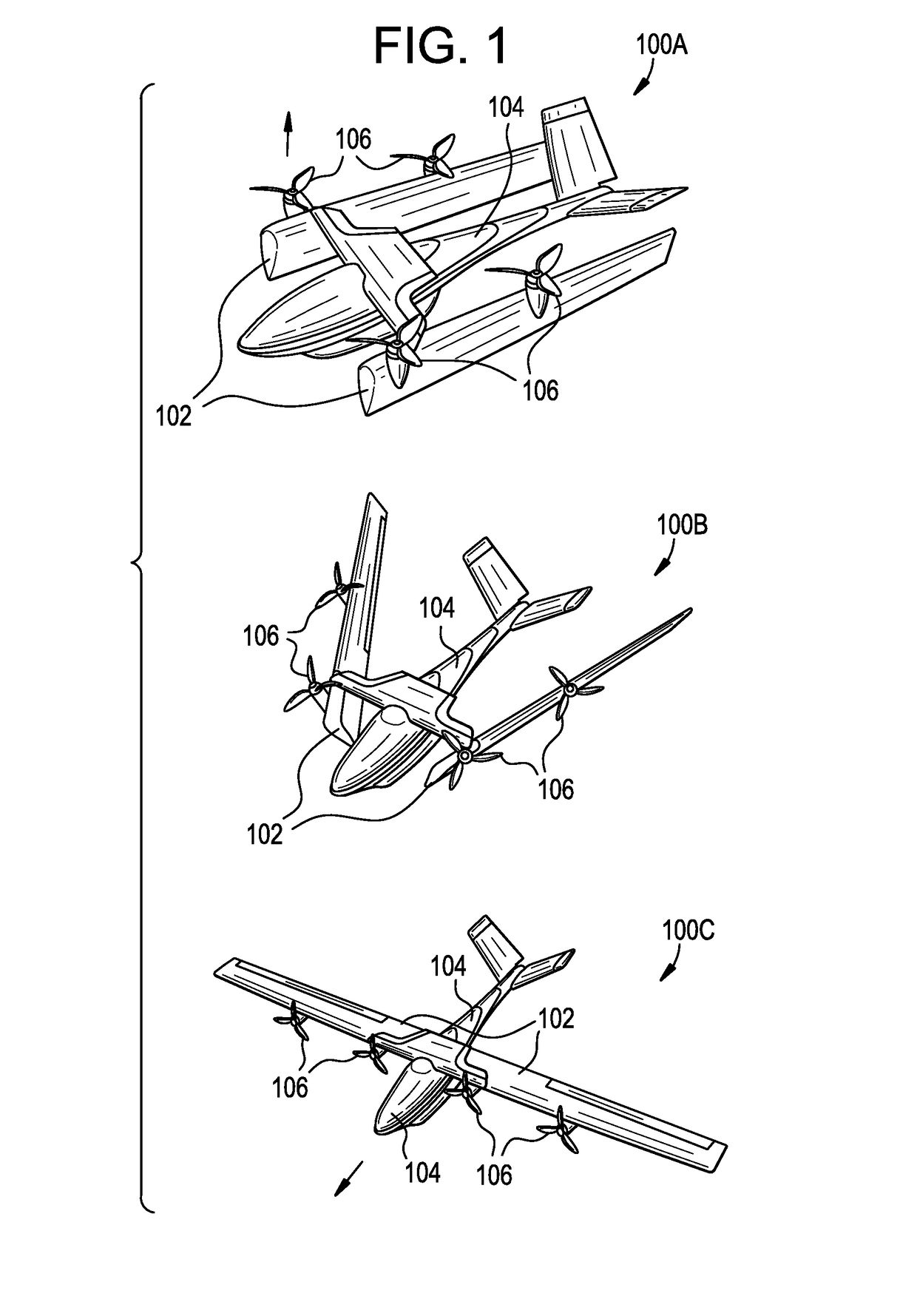
[0064]Certain exemplary embodiments will now be described to provide an overall understanding of the principles of the structure, function, manufacture, and use of the airframes disclosed herein. One or more examples of these embodiments are illustrated in the accompanying drawings. Those skilled in the art will understand that the embodiments specifically described herein and illustrated in the accompanying drawings are non-limiting exemplary embodiments and that the scope of the present invention is defined solely by the claims. The features illustrated or described in connection with one exemplary embodiment may be combined with the features of other embodiments. Such modifications and variations are intended to be included within the scope of the present invention.

[0065]Additionally, to the extent that linear, circular, or other dimensions are used in the description of the disclosed embodiments, such dimensions are not intended to limit the types of shapes that can be utilized....


PUM


Abstract

Airframes configured for stable in-flight transition between forward flight and vertical takeoff and landing are described herein. In one embodiment, an aircraft can include a fuselage, opposed wings extending from opposed sides of the fuselage, and a plurality of engines. At least one engine can be mounted to each of the opposed wings and at least a portion of each opposed wing including at least one of the plurality of engines can rotate relative to the fuselage around a rotation axis that is non-perpendicular and transverse to a longitudinal axis of the fuselage. Rotating portions of the wings including at least one of the plurality of engines in the described manner can provide a stable and smooth transition between vertical and forward flight.

Description

CROSS-REFERENCE TO RELATED APPLICATIONS[0001]This application claims the benefit of U.S. Provisional Application No. 62 / 490,814, filed Apr. 27, 2017, which is hereby incorporated by reference in its entirety.FIELD OF INVENTION[0002]This disclosure relates to the fields of aircraft and aerial vehicles. More particularly, this disclosure relates to an airframe capable of vertical takeoff and landing with engines mounted on rotatable wings.BACKGROUND[0003]Airframes with high aspect ratio fixed wings, e.g., wings rigidly attached to a fuselage wherein a laterally extending length, or span, of the wing is much greater than a distance between its leading and trailing edges, or chord, can be reliable and efficient in forward flight. These airframes can have several disadvantages as well, including difficulty maneuvering at slow speeds and the need for runway or other runout for takeoff and landing. Prior attempts to address these issues have included airframes with tilting nacelles that ho...

Claims


Application Information

Patent Timeline
Patent Type & Authority Applications(United States)
IPC IPC(8): B64C29/00B64C3/38B64D27/24B64D27/12B64C25/34B64C25/54
CPCB64C29/0033B64C3/38B64D27/24B64D27/12B64C25/34B64C25/54B64C3/56B64C27/26B64C27/28B64C37/00Y02T50/60Y02T50/40B64C3/42
Inventor PETROV, VAL
Owner PTERODYNAMICS INC
Why Eureka
Try Eureka