
Control method and drive control apparatus of hydraulic injection molding machine

a technology control method, which is applied in the direction of hydraulic injection molding machine speed control, accurate position control and speed control, etc., can solve the problems of trouble such as breakage or damage, and achieve the effect of improving control accuracy and stability to the target position, reducing the molding cycle, and improving molding quality

Active Publication Date: 2021-01-05
NISSEI PLASTIC IND CO LTD
View PDF13 Cites 0 Cited by
  • Summary
  • Abstract
  • Description
  • Claims
  • Application Information

AI Technical Summary

Benefits of technology

The present invention provides a control method and a drive control apparatus for a hydraulic injection molding machine. The technical effects of this invention include improved control accuracy and stability to the target position, reduced molding cycle, improved energy saving, and improved productivity and mass productivity. The invention can be applied to both the movement of the movable unit and the mold clamping operation. The stop position can be set in a more versatile manner, and a predetermined speed control pattern can be set to improve control accuracy and reduce fluctuation of the position and time of the movement. This can contribute to a hydraulic circuit having a reduced cost and a simpler and smaller circuit configuration.

Problems solved by technology

Generally, when a hydraulic injection molding machine is compared with an electric injection molding machine, it is difficult to provide accurate position control and speed control with the hydraulic injection molding machine.
For example, when it is assumed that the hydraulic driving actuator is a mold opening / closing cylinder provided on a mold clamping apparatus, even when the position is subjected to feedback control, the mold clamping position (metal mold closing position) or the mold closing time fluctuates depending on each shot and a movable mold collides with a fixed mold to cause troubles such as breakage or damage.

Method used


Image

  • Control method and drive control apparatus of hydraulic injection molding machine
  • Control method and drive control apparatus of hydraulic injection molding machine
  • Control method and drive control apparatus of hydraulic injection molding machine

Examples


Embodiment Construction

[0041]Next, the following section will describe the best embodiment according to the present invention in detail with reference to the drawings.

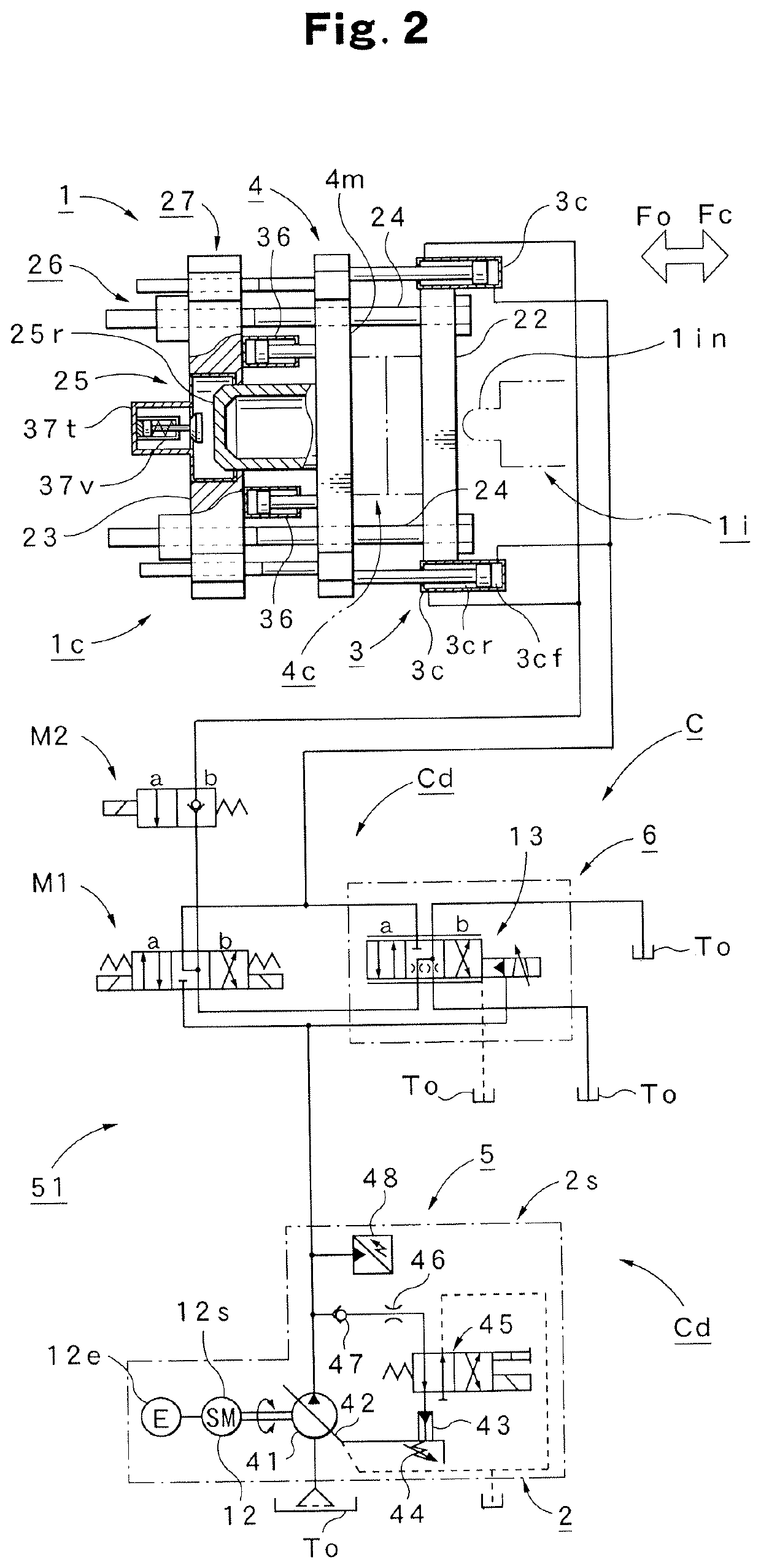
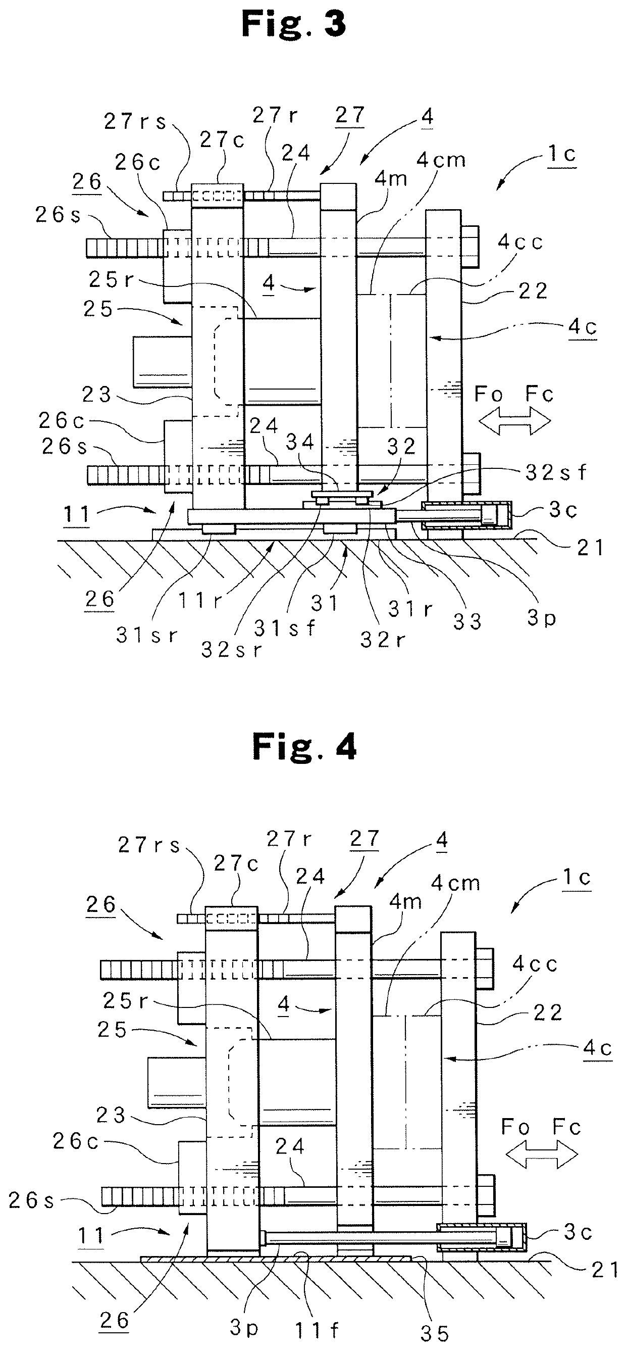
[0042]First, the following section will describe the configuration of the mold clamping apparatus 1c provided in a preferred hydraulic injection molding machine 1 using the control method according to this embodiment with reference to FIG. 2 to FIG. 4.

[0043]In FIG. 2, the reference numeral 1 denotes a hydraulic injection molding machine that includes the mold clamping apparatus 1c and an injection apparatus 1i a part of which is shown by the virtual line. FIG. 3 and FIG. 4 illustrate the mold clamping apparatus 1c . . . preferably using the control method according to this embodiment (in particular, two types of mold clamping apparatuses 1c and 1c including different movable unit support mechanisms 11 . . . ), respectively.

[0044]The mold clamping apparatus 1c shown in FIG. 3 has a basic configuration including a stationary platen 22 fixed on...


PUM

PropertyMeasurementUnit
flow rateaaaaaaaaaa
speedaaaaaaaaaa
moving resistanceaaaaaaaaaa

Abstract

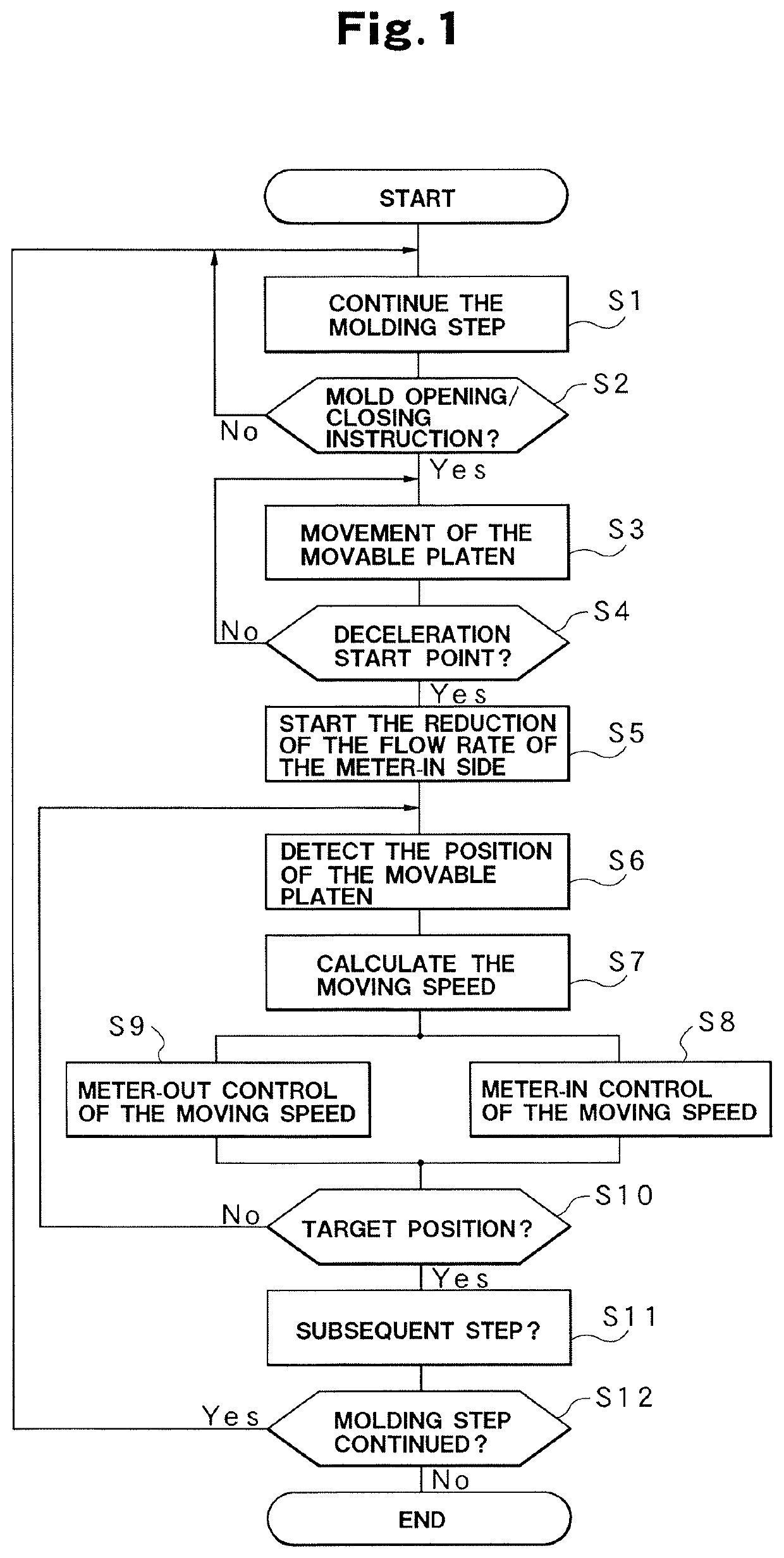
When the deceleration start point is reached, the meter-in side of the hydraulic driving actuator is subjected to a flow rate control to thereby start the deceleration control processing. The position to which the movable unit is moved is detected to use a speed instruction corresponding to the movement position to subject the hydraulic driving actuator to a meter-in control. The position to which the movable unit is moved is detected to calculate the moving speed of the movable unit. Based on the speed instruction, the moving speed is subjected to the feedback control using the meter-out control to the hydraulic driving actuator.

Description

TECHNICAL FIELD[0001]The present invention relates to a control method of and a drive control apparatus of a hydraulic injection molding machine preferably used for a control to drive a hydraulic driving actuator by a hydraulic pump to move a movable unit.BACKGROUND ART[0002]Generally, when a hydraulic injection molding machine is compared with an electric injection molding machine, it is difficult to provide accurate position control and speed control with the hydraulic injection molding machine. Specifically, in the case of the hydraulic injection molding machine, the use of hydraulic oil and a hydraulic driving actuator causes the hydraulic oil to have a varied viscosity or volume for example depending on the temperature and causes the hydraulic driving actuator to have an inertia force. These physical behaviors have a direct influence on the control accuracy and the responsiveness. When the hydraulic pump is a variable discharge-type hydraulic pump for which the rotation number ...

Claims


Application Information

Patent Timeline
Patent Type & Authority Patents(United States)
IPC IPC(8): B29C45/82B22D17/26B29C33/24B29C45/67B29C43/58B29C45/80
CPCB22D17/266B29C33/24B29C45/67B29C45/82B29C45/80B29C2043/5808B29C2945/76083B29C2945/76227B29C2945/76595B29C2945/76705B29C43/32B29C45/76B29C2945/7623B29C2945/76387B29C2945/76394B29C2945/76397B22D17/26
Inventor MIYAZAKI, HIROYUKISAKAKI, SATOMIHAYASHI, KENICHIKOMAMURA, ISAMU
Owner NISSEI PLASTIC IND CO LTD
Learn More