
Eureka
For R&D, Eureka makes reading and utilizing patents & technical documents easy.
Eureka AIR
Designed for self-driven R&D workflows. Generate viable solutions, solve complex R&D challenges, empower your innovation with AI.

Eureka Materials
Designed for material experts only. Revolutionize your material R&D, from search, analyze, to developing new materials.

TechResearch
Generate reliable direction feasibility study reports for your R&D in just a few steps.

TechSeek
Discover and master advanced knowledge NOW. Basics, ideas, possibilities, all at once.

TechMind
As an expert in R&D Theories, TechMind can generates customized viable solutions instantly.

TechRisk
Analyze your overall solution with one click, know your potential R&D risks in advance.

TechMonitor
Get weekly tech updates, stay abreast of the latest tech innovations and key insights.
Radiographic imaging apparatus, radiographic imaging system and information processing method
- Summary
- Abstract
- Description
- Claims
- Application Information
AI Technical Summary
Benefits of technology
Problems solved by technology
Method used
Image

Examples
first embodiment
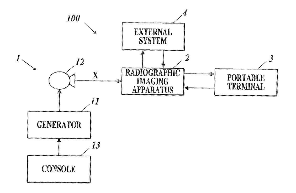
[0031]First, a first embodiment of a radiographic imaging system of the present invention is described with reference to FIG. 1 to FIG. 7.
[Configuration of Radiographic Imaging System]
[0032]First, configuration of a radiographic imaging system 100 of this embodiment is described. FIG. 1 is a schematic block diagram of the radiographic imaging system 100 of this embodiment.
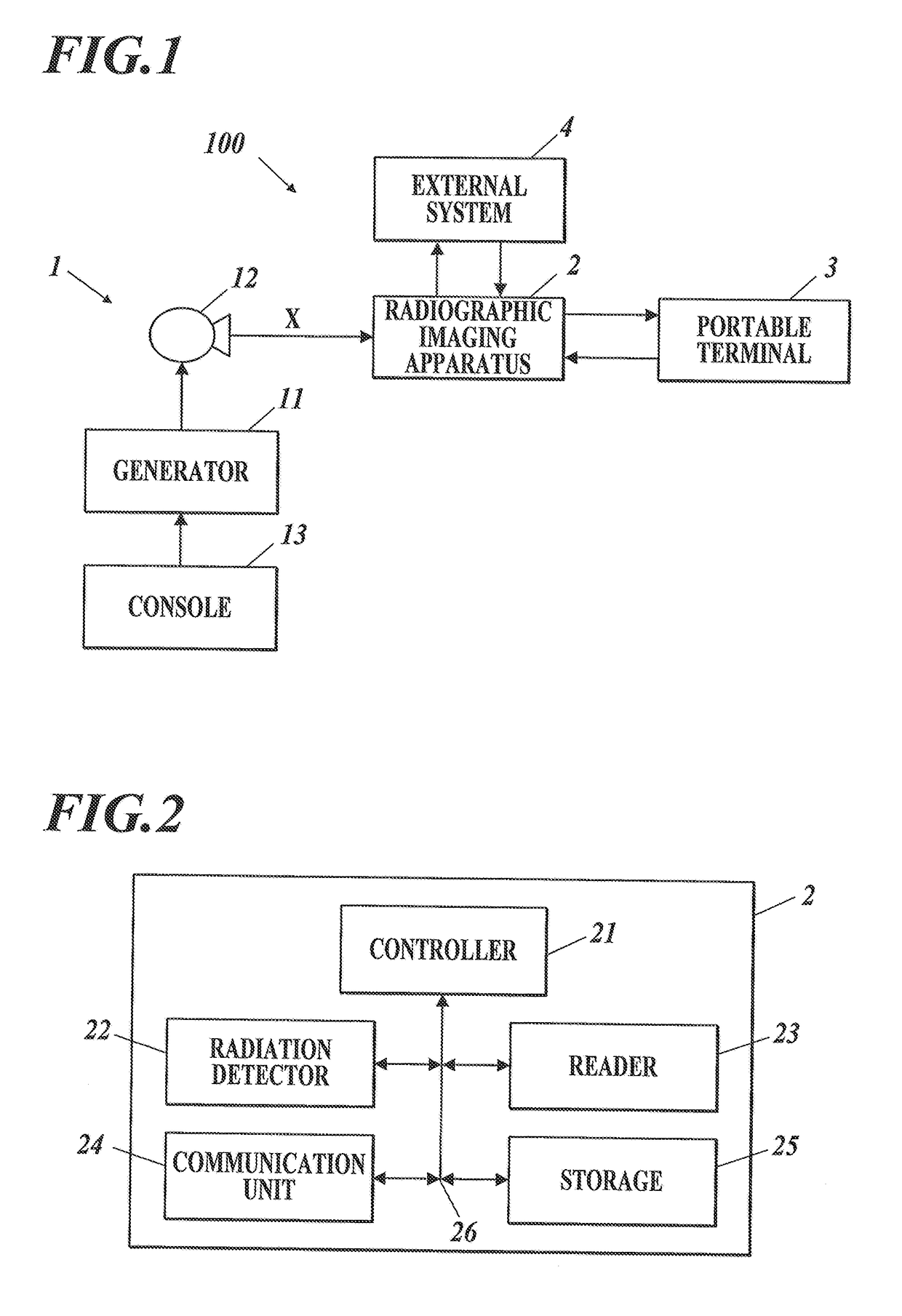
[0033]As shown in FIG. 1, the radiographic imaging system 100 of this embodiment includes a radiation emission apparatus 1, a radiographic imaging apparatus 2 and a portable terminal 3.
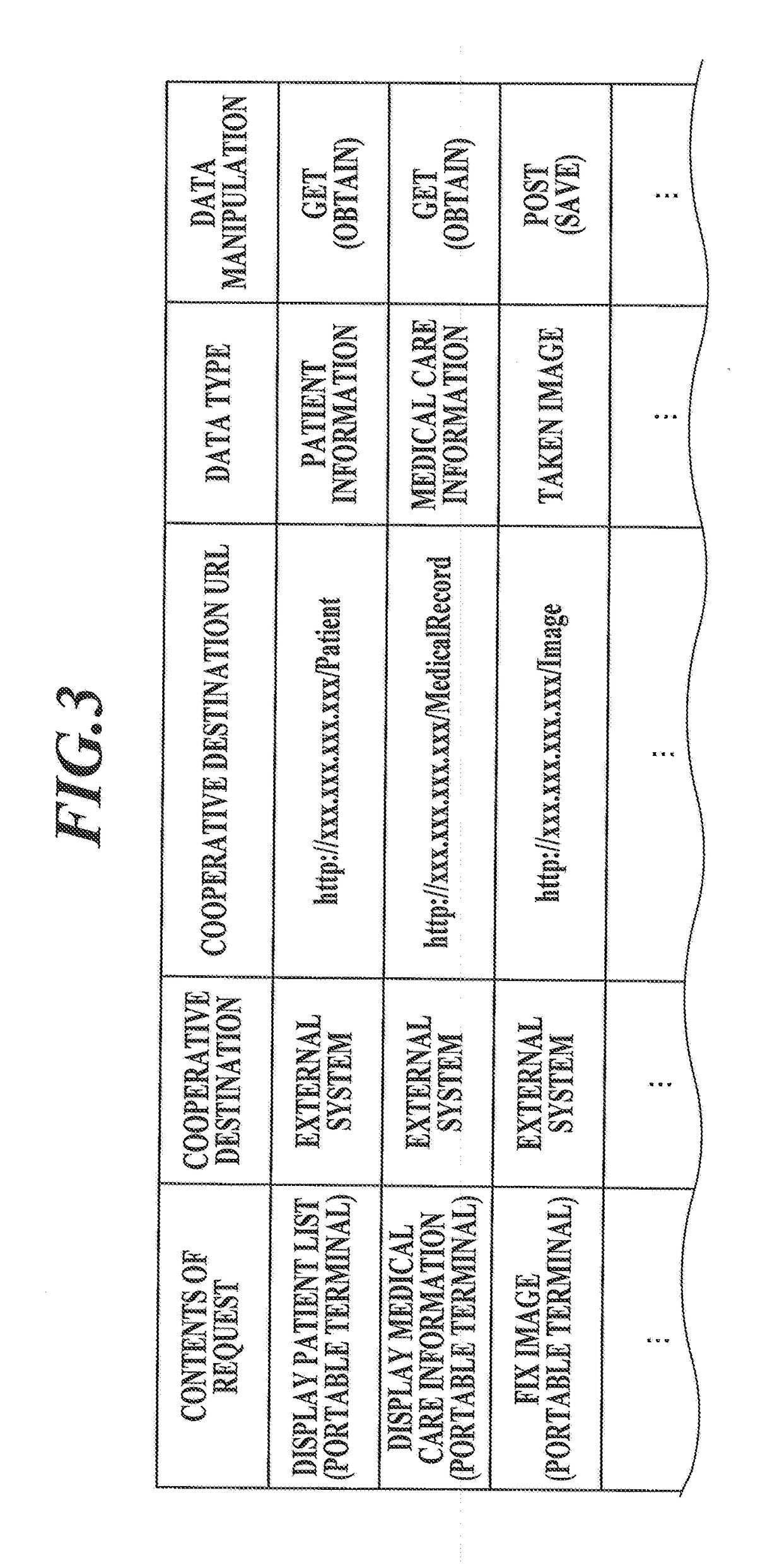
[0034]The radiographic imaging system 100 does not require a console that controls the radiographic imaging apparatus 2, and can directly communicate with an external system 4. The external system 4 herein is a generic term used to refer to an electronic medical record system, a radiology information system (RIS), a picture archiving and communication system (PACS), an image processing system and so forth.
[0035]The radiation emission...
second embodiment
[0140]Next, a second embodiment of a radiograph display system (e.g. the radiographic imaging system in the first embodiment) of the present invention is described with reference to FIG. 8 to FIG. 13.
[0141]FIG. 8 is a block diagram showing main components of a radiographic imaging apparatus of this embodiment. FIG. 9 is a block diagram showing main components of a terminal apparatus of this embodiment.
[0142]FIG. 10 is a schematic block diagram showing software configuration of an HTTP server function and a Web server function of a radiograph display system 1001 of this embodiment.
[0143]The radiograph display system 1001 (FIG. 10) of this embodiment includes: a portable radiographic imaging apparatus 1002 that performs radiographic imaging using a radiation detector 1021 (FIG. 8), thereby obtaining taken images; and a terminal apparatus 1004 (FIG. 9) that communicates with the radiographic imaging apparatus 1002, wherein the images taken by the radiographic imaging apparatus 1002 can...
third embodiment
[0241]Next, a third embodiment of the radiograph display system of the present invention is described with reference to FIG. 14 to FIG. 17.
[0242]The third embodiment is different from the second embodiment mainly in function and role of the terminal apparatus 1004 and the radiographic imaging apparatus 1002. Hereinafter, the points different from the second embodiment are described mainly.
[0243]FIG. 14 is a schematic block diagram showing software configuration of an HTTP server function and a Web server function of a radiograph display system 1010 of this embodiment.
[0244]As shown in FIG. 14, in this embodiment, the radiographic imaging apparatus 1002 includes an imaging order information storage 1037 which stores therein imaging order information (patient name(s), imaging site(s), etc.) on imaging in the form to be providable for the terminal apparatus 1004.
[0245]The imaging order information is stored in the imaging order information storage 1037 in advance by being sent from the...
PUM
 Abstract
Description
Claims
Application Information
 - R&D Engineer
- R&D Manager
- IP Professional
- Industry Leading Data Capabilities
- Powerful AI technology
- Patent DNA Extraction
Browse by: Latest US Patents, China's latest patents, Technical Efficacy Thesaurus, Application Domain, Technology Topic, Popular Technical Reports.
© 2024 PatSnap. All rights reserved.Legal|Privacy policy|Modern Slavery Act Transparency Statement|Sitemap|About US| Contact US: help@patsnap.com