Method for Releasing a First Brake Device Which Is Actuated by Electric Motor, Control Unit for a Brake System of a Vehicle, Brake System for a Vehicle, and Vehicle Having a Brake System of This Type

Active Publication Date: 2018-11-15
ROBERT BOSCH GMBH
View PDF8 Cites 0 Cited by
  • Summary
  • Abstract
  • Description
  • Claims
  • Application Information

AI Technical Summary

Benefits of technology

[0004]It is the object of the invention to provide a method for releasing a first electric motor-actuated brake device, a control unit for a brake system, a brake system for a vehicle, and a vehicle wi

Problems solved by technology

In this case, in particular occur it can that the time to build up a clamping force is in conflict with a rapid start-up demand by a driver of a vehicle.
It appears that a main reason for the comparatively slow release of an electric motor-actuated brake device is that systems of this type are designed to be self

Method used


Image

  • Method for Releasing a First Brake Device Which Is Actuated by Electric Motor, Control Unit for a Brake System of a Vehicle, Brake System for a Vehicle, and Vehicle Having a Brake System of This Type
  • Method for Releasing a First Brake Device Which Is Actuated by Electric Motor, Control Unit for a Brake System of a Vehicle, Brake System for a Vehicle, and Vehicle Having a Brake System of This Type
  • Method for Releasing a First Brake Device Which Is Actuated by Electric Motor, Control Unit for a Brake System of a Vehicle, Brake System for a Vehicle, and Vehicle Having a Brake System of This Type

Examples


Example

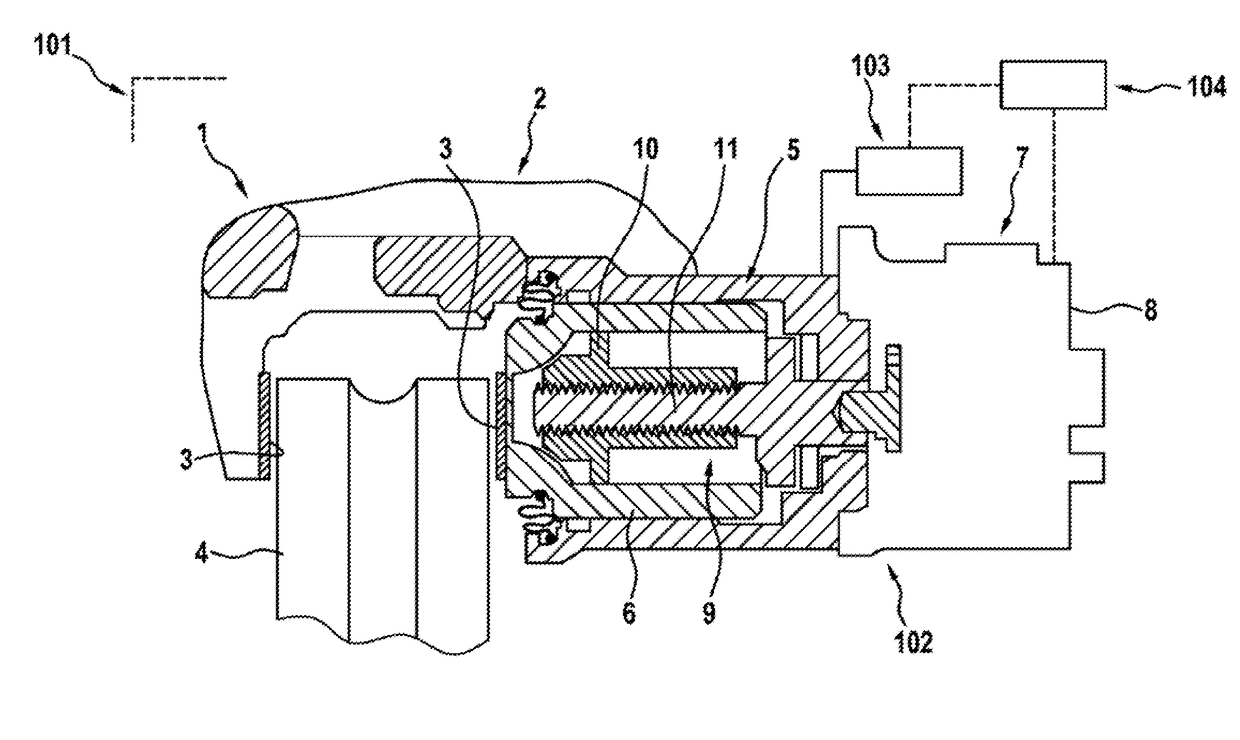
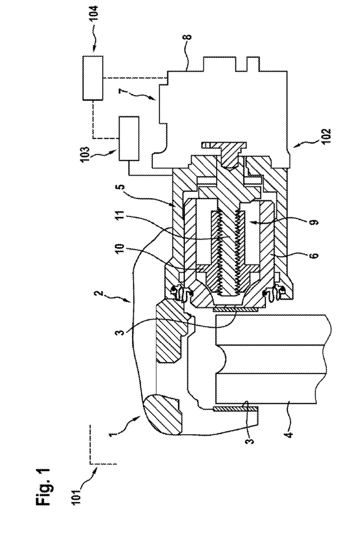
[0035]FIG. 1 shows in a simplified sectional representation a brake system 1 of a vehicle 101 with a first electric motor-actuated brake device 102 and a second brake device 103 that is not actuated by electric motor. The brake system 1 comprises a disk brake, wherein a brake caliper 2 is provided that carries brake linings 3, between which a brake disk 4 that is joined to a wheel of the vehicle 101 can be jammed or clamped. For this purpose, a hydraulic actuator 5 is associated with the brake caliper 2 that is associated with the second brake device 103, which is embodied here as a hydraulic brake device, the actuator 5 comprising a brake piston that is hydraulically actuated to clamp the brake disk 4 between the brake linings 3 when required. As a result, in particular with the vehicle 101 in the driving mode, a braking torque is applied to the brake disk 4 and thus to the wheels, which is used to decelerate the vehicle 101.

[0036]The first brake device 102 is embodied as a parking...


PUM


Abstract

A method for releasing a first electric motor-actuated brake device for a vehicle includes actuating a second brake device for the vehicle in a clamping direction with a first brake device in a clamped state in order to produce a predetermined clamping force on a brake piston that is associated with the first brake device and the second brake device in common. The method further includes actuating the first brake device in a release direction before the second brake device reaches the predetermined clamping force.

Description

[0001]The invention concerns a method for releasing an electric motor-actuated brake device, a control unit for a brake system of a vehicle, a brake system for a vehicle with a control unit of this type, and a vehicle with a brake system of this type.Prior Art[0002]In the case of an electric motor-actuated brake device, a clamping force is preferably produced by means of a spindle-nut system, wherein the spindle-nut system is preferably disposed in a brake piston. Because of the electromechanical actuation and the design-related mechanical transmission by means of gear stages, a brake device of this type has longer application times for clamping and release processes, in particular compared to purely hydraulic brake devices. In this case, in particular occur it can that the time to build up a clamping force is in conflict with a rapid start-up demand by a driver of a vehicle. As an example, in order to show the potential of said method, a so-called racing start can be considered tha...

Claims


Application Information

Patent Timeline
IPC IPC(8): B60T13/66B60T13/58B60T13/74
CPCB60T13/662B60T13/588B60T13/741F16D55/226B60Y2400/81
Inventor WOLFF, HELMUTENGLERT, ANDREAS
Owner ROBERT BOSCH GMBH
Why Eureka
Try Eureka