Electronic device having pressure sensor

a technology of electronic devices and pressure sensors, applied in piezoelectric/electrostrictive/magnetostrictive devices, pulse techniques, instruments, etc., can solve problems such as undesired operation and touch error of users, and achieve the effect of improving sensing efficiency and piezoelectric characteristics

Inactive Publication Date: 2018-11-15
MODA INNOCHIPS CO LTD
View PDF7 Cites 16 Cited by
  • Summary
  • Abstract
  • Description
  • Claims
  • Application Information

AI Technical Summary

Benefits of technology

[0023]An electronic device in accordance with an exemplary embodiment may include a window, a display part, and a pressure sensor, and at least one or more pressure sensors may be provided in at least one place under the display part and under the window. In addition, the pressure sensor may have a piezoelectric layer between first and second electrode layers spaced apart from each other, and the piezoelectric layer may be provided with a plurality of plate-like single-crystal piezoelectric bodies. Since the plate-like piezoelectric bodies are used, the pressure sensor may have piezoelectric characteristics which are better than that employing typical piezoelectric powder. Thus, a minute pressure may also be easily sensed, and thus the sensing efficiency may be improved.
[0024]In addition, in the pressure sensor in accordance with an exemplary embodiment, the piezoelectric layer may have a cutaway portion for each cell unit, and an elastic layer may further be formed in the cutaway portions. The plurality of cutaway portions are formed in the piezoelectric layer, and thus, the pressure sensor may have a flexible characteristic.
[0025]Meanwhile, the electronic device in accordance with an exemplary embodiment further includes a touch sensor, and may more precisely detect the position and the pressure by the cooperation of the touch sensor and the pressure sensor. That is, the touch sensor and the pressure sensor simultaneously detect coordinates in the horizontal direction (that is, X- and Y-directions), and the pressure sensor detects the pressure in the vertical direction (that is, a Z-direction), and thus, the touch position may be more precisely detected.

Problems solved by technology

However, in the electronic device using only a touch sensor, a touch error of a user occurs, and an undesired operation may be performed.

Method used


Image

  • Electronic device having pressure sensor
  • Electronic device having pressure sensor
  • Electronic device having pressure sensor

Examples


Embodiment Construction

[0043]Hereinafter, exemplary embodiments of the present invention will be described in detail with reference to the accompanying drawings. The present invention may, however, be embodied in different forms and should not be construed as limited to the embodiments set forth herein. Rather, these embodiments are provided so that this invention will be thorough and complete, and will fully convey the scope of the present invention to those skilled in the art.

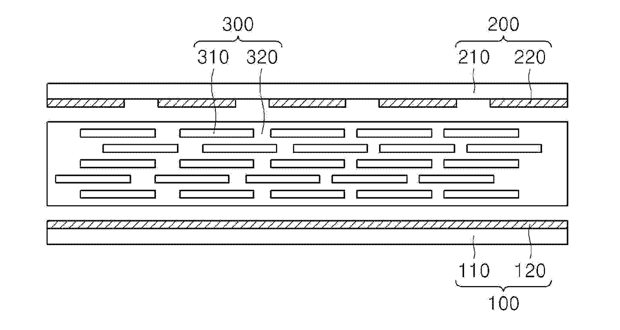
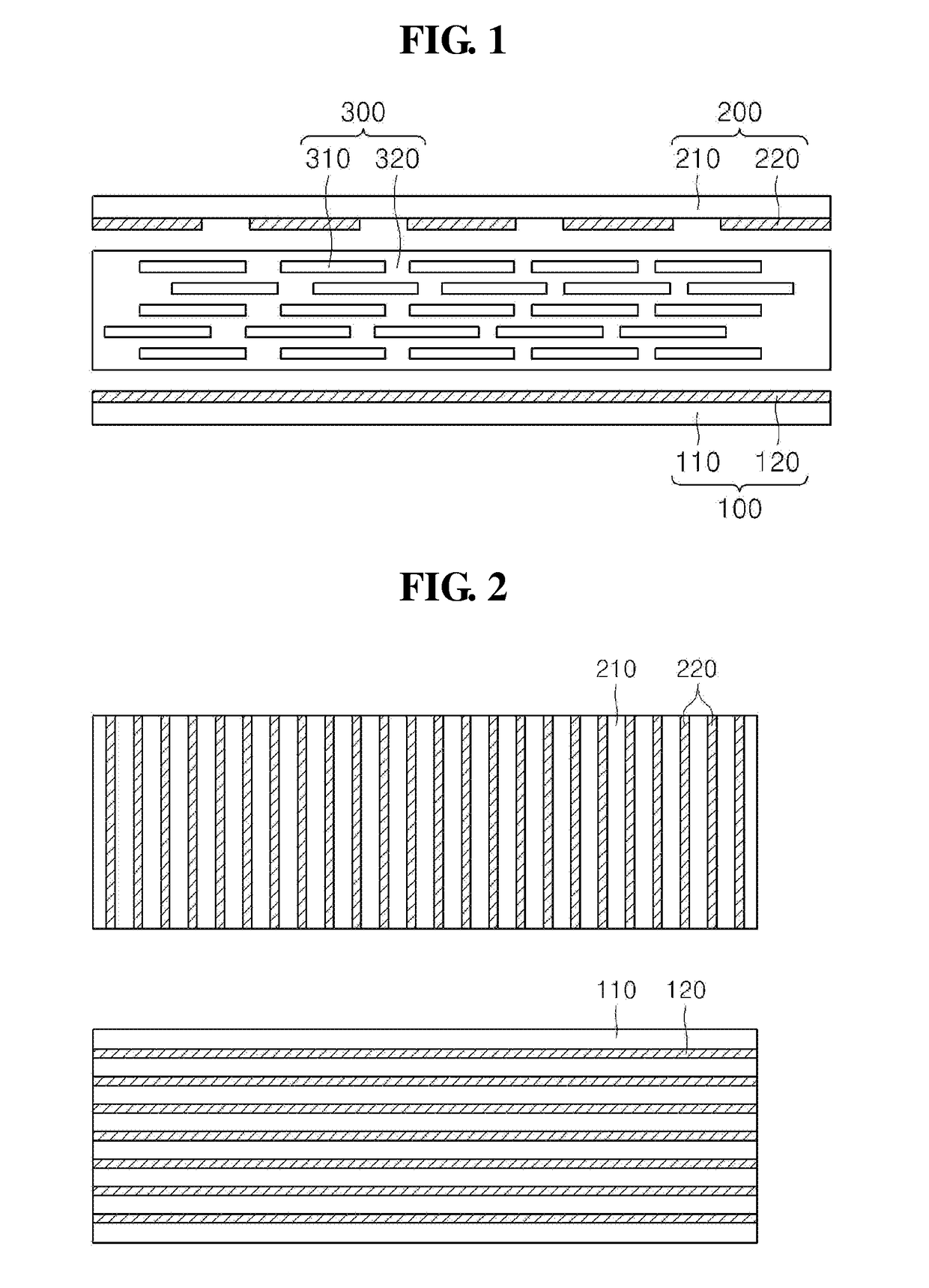
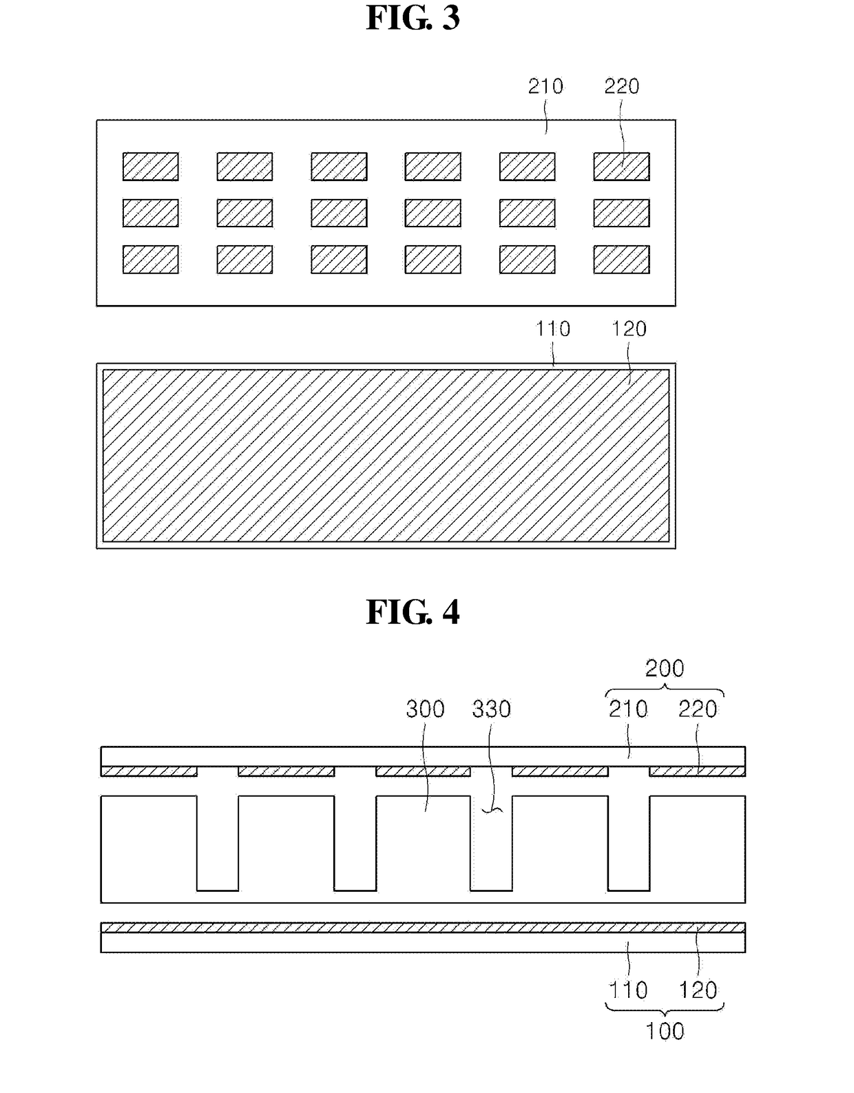
[0044]FIG. 1 is a cross-sectional view of a pressure sensor in accordance with a first exemplary embodiment, and FIGS. 2 and 3 are schematic views of first and second electrode layers of a pressure sensor.

[0045]Referring to FIG. 1, a pressure sensor in accordance with an exemplary embodiment includes: first and second electrode layers 100 and 200 which are spaced apart from each other; and a piezoelectric layer 300 provided between the first and second electrode layers 100 and 200. Here, the piezoelectric layer 300 may be provided ...


PUM

PropertyMeasurementUnit
porosityaaaaaaaaaa
sizesaaaaaaaaaa
porosityaaaaaaaaaa

Abstract

The present disclosure proposes an electronic device including: a window; a display part configured to display an image through the window; and a pressure sensor configured to detect a position and a pressure of a touch input applied through the window, wherein the pressure sensor includes: first and second electrode layers provided spaced apart from each other; and a piezoelectric layer provided between the first and second electrode layers, and the piezoelectric layer includes a plurality of cutaway portions formed with predetermined widths and depths.

Description

TECHNICAL FIELD[0001]The present disclosure relates to an electronic device, and more particularly, to an electronic device provided with a pressure sensor capable of preventing a touch input error while performing a predetermined function by a user's touch.BACKGROUND ART[0002]In order to operate electronic devices such as various mobile communication terminals, various types of input devices are being used. For example, input devices such as buttons, keys, and a touch screen panel are being used. A touch screen panel, that is, a touch sensor detects the touch of a human body and enables an electronic device to be easily and simply operated only by a light touch. Therefore, the use thereof is being increased. That is, the touch sensor has a technical means which detects and recognizes touch or non-touch of a human body (finger) or a pen using the detection of human body current due to the touch or a change in pressure, temperature, or the like. Such a touch input device is not only ...

Claims


Application Information

Patent Timeline
Patent Type & Authority Applications(United States)
IPC IPC(8): G06F3/041H01L41/047G02F1/1335G02F1/1343G02F1/1333
CPCG06F3/0414G06F3/0412H01L41/047G02F1/133602G02F1/133553G02F1/1343G02F1/13338H10N30/87H10N30/852H10N30/302G01L1/16H03K17/964
Inventor PARK, IN KILJUNG, JUN HO
Owner MODA INNOCHIPS CO LTD
Why Eureka
Try Eureka