
Method and system for leading edge auxiliary turbine vanes

a technology of auxiliary turbines and valves, applied in the direction of blade accessories, climate sustainability, sustainable transportation, etc., can solve the problems of shortening the life expectancy of airfoils, affecting engine performance, efficiency and/or operability, and high three-dimensional separation flows

Active Publication Date: 2018-11-22
GENERAL ELECTRIC CO
View PDF10 Cites 2 Cited by
  • Summary
  • Abstract
  • Description
  • Claims
  • Application Information

AI Technical Summary

Benefits of technology

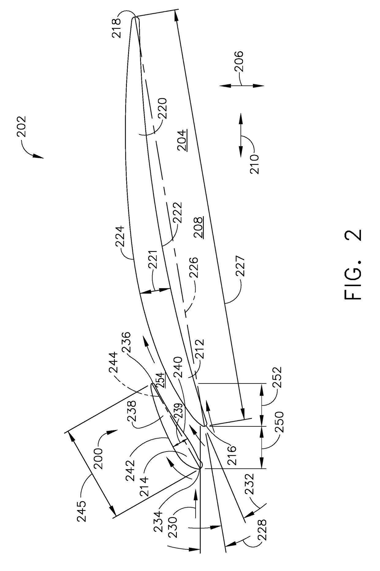
The patent describes a gas turbine engine with a row of stationary turbine vanes that includes main vanes and auxiliary vanes. The main vanes are positioned radially inward from the machine casing and have a specific height and chord length. The auxiliary vanes are positioned between the main vanes and also have a specific height and chord length. A flow channel is defined between the pressure side of the auxiliary vane and the suction side of the main vane. The technical effect of this design is to improve the performance and efficiency of the gas turbine engine by optimizing the flow of fluid through the vane pair and reducing the negative incidence of the vane.

Problems solved by technology

During the wide range of operational conditions, turbine stator airfoils or vanes may operate at negative incidence, which can result in highly three dimensional separated flows on the pressure surface of the vanes of the turbine stator.
The operation of turbine vanes at negative incidence in variable cycle engines can result in conditions that could adversely affect engine performance, efficiency, and / or operability or could shorten the life expectancy of the airfoils.
Such separation may introduce an undesirable vibratory mode to the airfoil or downstream airfoils.
Additionally, the separation may cause a significant loss in turbine and / or engine overall performance.

Method used


Image

  • Method and system for leading edge auxiliary turbine vanes
  • Method and system for leading edge auxiliary turbine vanes
  • Method and system for leading edge auxiliary turbine vanes

Examples


Embodiment Construction

[0016]In the following specification and the claims, reference will be made to a number of terms, which shall be defined to have the following meanings.

[0017]The singular forms “a,”“an,” and “the” include plural references unless the context clearly dictates otherwise.

[0018]“Optional” or “optionally” means that the subsequently described event or circumstance may or may not occur, and that the description includes instances where the event occurs and instances where it does not.

[0019]Approximating language, as used herein throughout the specification and claims, may be applied to modify any quantitative representation that could permissibly vary without resulting in a change in the basic function to which it is related. Accordingly, a value modified by a term or terms, such as “about,”“approximately,” and “substantially,” are not to be limited to the precise value specified. In at least some instances, the approximating language may correspond to the precision of an instrument for m...


PUM


Abstract

An apparatus and method of managing negative incidence of an airfoil are provided. The apparatus includes a first row of stationary turbine main vanes and a second row of auxiliary vanes extending radially inwardly from a stationary casing of the turbine proximate the adjacent leading edge of the main vane. The apparatus also includes a flow channel defined between a pressure side of an auxiliary vane of the second row of auxiliary vanes and a suction side of an adjacent main vane of the row of stationary turbine main vanes.

Description

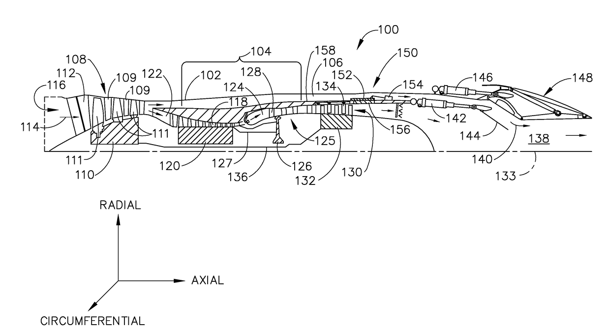
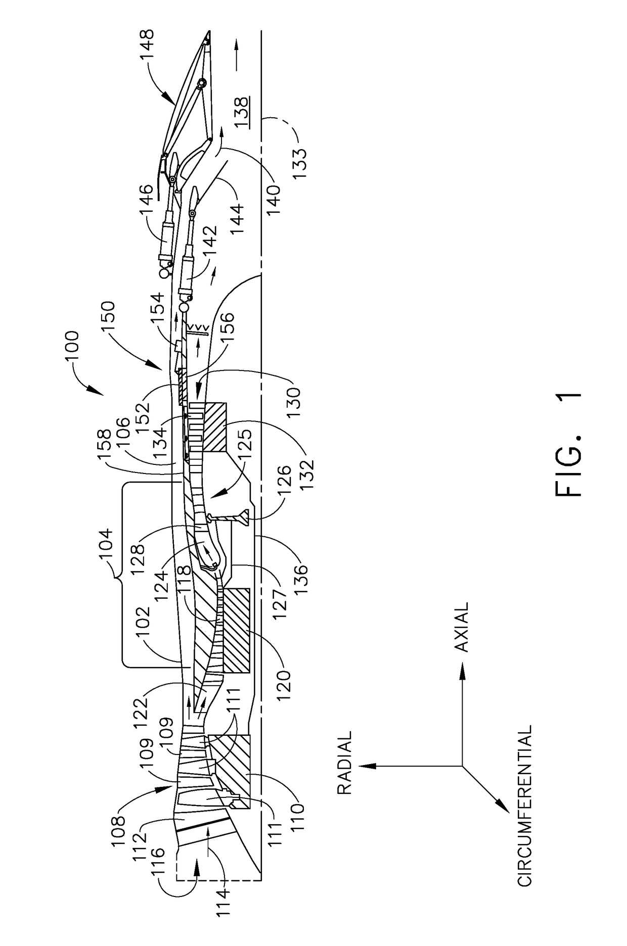
BACKGROUND[0001]The field of the disclosure relates generally to gas turbine engines and, more particularly, to a method and system for managing negative incidence in turbine stator vanes using auxiliary airfoils.[0002]At least some known gas turbine engines, such as, for example, variable cycle engines or adaptive cycle engines, are configured to operate efficiently under mixed flight conditions, such as subsonic, transonic and supersonic, and can effectively change the operating parameters of the compressors and / or turbines in a controlled way. During the wide range of operational conditions, turbine stator airfoils or vanes may operate at negative incidence, which can result in highly three dimensional separated flows on the pressure surface of the vanes of the turbine stator. The operation of turbine vanes at negative incidence in variable cycle engines can result in conditions that could adversely affect engine performance, efficiency, and / or operability or could shorten the li...

Claims


Application Information

Patent Timeline
Patent Type & Authority Applications(United States)
IPC IPC(8): F01D9/04
CPCF05D2240/121F01D9/041F01D5/146Y02T50/60
Inventor LURIE, DAVID PAULABDELFATTAH, SHERIF ALYKADRYCASTILLO, MICHAEL JULIANDIPIETRO, JR., ANTHONY LOUISWADIA, ASPI RUSTOMHEITLAND, GREGORY BURR
Owner GENERAL ELECTRIC CO
Learn More