Motor vehicle high voltage energy accumulator

a high-voltage electric and accumulator technology, applied in the direction of battery/fuel cell control arrangement, cell components, battery/fuel cell, etc., can solve the problems of insufficient structural strength of energy accumulator housings alone, fundamental fire risk, etc., and achieve high cooling performance and simple fluidic connection of energy accumulator to cooling circuit.

Active Publication Date: 2018-11-22
DR ING H C F PORSCHE AG
View PDF0 Cites 10 Cited by
  • Summary
  • Abstract
  • Description
  • Claims
  • Application Information

AI Technical Summary

Benefits of technology

[0023]According to a preferred refinement, the bottom wall adjoining the side wall or the adjoining top wall is fastened directly only on the side wall supporting structure plate and therefore connected only indirectly to the cooling structure plate. The cooling structure plate is thus directly connected only to the supporting structure plate. Since the cooling structure plate contributes at most to a small degree to the overall stability of the housing, a direct fixing of the cooling structure plate to the top wall or the bottom wall is unnecessary. Furthermore, stresses between the cooling structure plate and the supporting structure plate are avoided in this way. If the;side walls do not form the supporting structure walls but the bottom wall and the top wall form the supporting structure ails, the bottom wall and top wall supporting structure plates are directly connected to the relevant side walls.
[0024]At least one end wall lying in a transverse plane preferably has a cooling liquid connection, for example a cooling liquid inlet and / or a cooling liquid outlet. With particular preference, all the cooling liquid connections are arranged on a single end wall, with the result that the other end wall does not have a single cooling liquid connection. In this way, the fluidic connection of the energy accumulator to the cooling circuit is relatively simple.
[0025]In principle, the cooling structure plate can be arranged proximally from the supporting structure plate, that is to say on the housing inner side of the supporting structure plate. With particular preference, however, the cooling structure plate is arranged distally from the supporting structure plate, that is to say is arranged on the housing outer side of the as supporting structure plate. In this way, it is ensured that, in the event of a leakage at the abutment surface between the supporting structure plate and the cooling structure plate, the cooling liquid cannot pass into the housing interior, whereby the battery modules could be damaged or destroyed. Nevertheless, the direct wetting of the supporting structure plate by the cooling liquid makes it possible to achieve a high cooling performance.

Problems solved by technology

High-voltage electric energy accumulators for electrically driven vehicles operate with operating voltages of several 100 V and therefore fundamentally constitute a fire risk particularly in the event of a crash.
The aforementioned energy accumulator housings alone do not have sufficient structural strength with respect to lateral crash situations, which means, for example, that additional transverse webs have to be provided within the housing in order to improve the structural strength.

Method used


Image

  • Motor vehicle high voltage energy accumulator
  • Motor vehicle high voltage energy accumulator
  • Motor vehicle high voltage energy accumulator

Examples


second embodiment

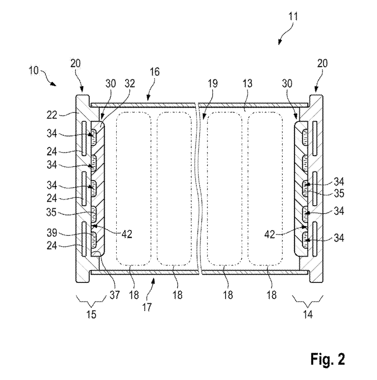
[0041]FIG. 3 illustrates the motor vehicle high-voltage energy accumulator 10′, which differs from the energy accumulator 10 according to the first exemplary embodiment only in terms of the structure of the two side walls 14′, 15′. In the second exemplary embodiment, the cooling structure plate 30′ is arranged distally from the supporting structure plate 20′. Therefore, the supporting structure metal body 22′ has the receiving trough 42′ on the outside. The plastic plate body 32′ of the cooling structure plate 30′ is inserted into the receiving trough 42′ from outside. This exemplary embodiment of the side walls 14′, 15′ has the advantage that, in the event of a leakage at the interface between the supporting structure plate 20′ and the cooling structure as plate 30′, the cooling liquid running out cannot pass into the interior 19. Nevertheless, the direct cooling liquid wetting of the supporting structure plate 20′ makes it possible to achieve a high cooling performance

third embodiment

[0042]FIG. 4 illustrates a motor vehicle high-voltage energy accumulator according to aspects of the invention in cross section. By comparison with the first two embodiments of FIGS. 2 and 3, in the embodiment illustrated in FIG. 4 the bottom wall 114′ and the top wall 115′ are designed as load-path-forming walls, whereas the remaining walls, namely the two side walls and the two end walls, are of thin-walled design and have only a small load path function, if any. Moreover, the structure of the top wall 115′ and of the bottom wall 114′ corresponds to the structure and the design of the side walls 15′, 14′ illustrated in FIG. 3. The reference signs which correspond with one another are each raised by 100 in FIG. 4 relative to the reference signs of FIG. 3. The embodiment in FIG. 4 thus represents a distal cooling analogous to FIG. 3. In a variation of the embodiment in FIG. 4, a proximal cooling as illustrated in FIG. 2 can also be used.

[0043]FIG, 5 illustrates a fourth exemplary em...


PUM

PropertyMeasurementUnit
thicknessaaaaaaaaaa
operating voltagesaaaaaaaaaa
wall thicknessaaaaaaaaaa

Abstract

A motor vehicle high-voltage energy accumulator having a housing with battery modules mounted inside, wherein the housing has a bottom wail, a top wail, a front end wail, a rear end wail, a left side wall, and a right side wall. In each case, two oppositely arranged wails of the>housing which are oriented in the longitudinal direction have load-path-forming supporting structure plates and cooling ducts through which cooling liquid flows. Here, the cooling ducts are either integrated directly into the supporting structure plate in the form of cavities or formed by the connection of a separate cooling structure plate to the supporting structure plate. The supporting structure plate and, where appropriate, the cooling structure plate increase the structural stability or the formation of cooling ducts.

Description

CROSS-REFERENCE TO RELATED APPLICATION[0001]This application claims priority to German Patent Application No. DE 10 2017 110 578.6, filed May 16, 2017, which is incorporated by reference herein in its entirety,FIELD OF THE INVENTION[0002]The invention relates to a motor vehicle high-voltage electric energy accumulator for storing electrical energy in an electrically or part-electrically driven vehicle.BACKGROUND OF THE INVENTION[0003]High-voltage electric energy accumulators for electrically driven vehicles operate with operating voltages of several 100 V and therefore fundamentally constitute a fire risk particularly in the event of a crash. The high-voltage energy accumulators are as a rule arranged in the vehicle floor and are therefore accommodated in battery housings which have a high structural stability, to be precise in particular with respect to lateral crash situations. Since the battery modules can significantly heat up during charging and during discharging, the high-vol...

Claims


Application Information

Patent Timeline
Patent Type & Authority Applications(United States)
IPC IPC(8): H01M2/10H01M10/6556H01M10/613H01M10/625H01M50/204H01M50/262
CPCH01M2/1077H01M10/6556H01M10/613H01M10/625B60L11/1877B60L11/1874H01M2220/20H01M10/6554H01M10/6568H01M50/262H01M50/204H01M10/647H01M10/6567B60L58/26B60L50/66Y02T10/70Y02E60/10
Inventor KELLNER, PHILIPPBOHLIEN, JENSKOHLER, LUKAS
Owner DR ING H C F PORSCHE AG
Why Eureka
Try Eureka