Moving picture coding device, moving picture coding method, and moving picture coding program, and moving picture decoding device, moving picture decoding method, and moving picture decoding program

a technology of moving picture and coding method, which is applied in the direction of digital video signal modification, electrical equipment, and picture communication, etc., can solve the problems of large difference between motion vectors, inability to achieve efficient coding, and increase in generated coding amount, so as to improve the coding efficiency of motion information and reduce processing load

Active Publication Date: 2018-11-29
NEC CORP
View PDF0 Cites 0 Cited by
  • Summary
  • Abstract
  • Description
  • Claims
  • Application Information

AI Technical Summary

Benefits of technology

[0008]The present invention is contrived in consideration of such situations, and an object thereof is to provide a technology having a small processing load and improved coding efficiency of the motion information in a case where coding is performed using the motion information of a neighboring block.

Problems solved by technology

However, in such a prediction method, since the position of the neighboring block to be referred to is limited, a difference between motion vectors is large when the prediction is incorrect, and there is a problem in that the amount of generated coding increases.
In addition, although the coding amount of the motion vector is reduced, the other motion information such as a predicted direction, a reference picture index, and the like is coded for each processing target block, and accordingly, there is a problem in that efficient coding is not achieved.
Accordingly, in a case where a plurality of neighboring blocks having the same motion information are included in reference neighboring block candidates, the number of kinds of motion information that can be represented by the reference neighboring block candidates is small, and, consequently, the improvement of the coding efficiency is not achieved.

Method used


Image

  • Moving picture coding device, moving picture coding method, and moving picture coding program, and moving picture decoding device, moving picture decoding method, and moving picture decoding program
  • Moving picture coding device, moving picture coding method, and moving picture coding program, and moving picture decoding device, moving picture decoding method, and moving picture decoding program
  • Moving picture coding device, moving picture coding method, and moving picture coding program, and moving picture decoding device, moving picture decoding method, and moving picture decoding program

Examples


embodiment 1

[0073][Entire Configuration of Moving Picture Coding Device]

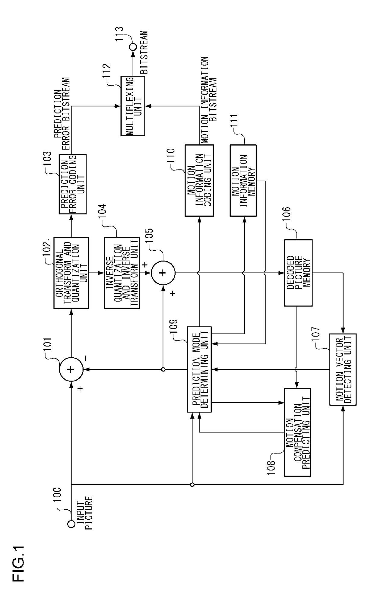
[0074]FIG. 1 is a diagram that illustrates the configuration of a moving picture coding device according to Embodiment 1 of the present invention. Hereinafter, the operation of each unit will be described. The moving picture coding device according to Embodiment 1 includes: an input terminal 100; a subtraction unit 101; an orthogonal transform and quantization unit 102; a prediction error coding unit 103; an inverse quantization and inverse transform unit 104; an addition unit 105; a decoded picture memory 106; a motion vector detecting unit 107; a motion-compensated prediction unit 108; a prediction mode determining unit 109; a motion information coding unit 110; a motion information memory 111; a multiplexing unit 112; and an output terminal 113.

[0075]A picture signal of a prediction block that is a coding processing target is cut out from a picture signal input from the input terminal 100 based on position information of...

embodiment 2

[0239]Next, Embodiment 2 of the present invention will be described. In Embodiment 2, a merging prediction candidate removing operation is different from that of Embodiment 1. The configurations and processes other than the merging prediction candidate removing operation are the same as those of Embodiment 1, and here, only a difference in the merging motion information list removing process performed by the merging motion information candidate list removing unit 1001 illustrated in FIG. 10 from that of Embodiment 1 will be described.

[0240]FIG. 31 is a flowchart that illustrates the detailed operation performed in the merging motion information candidate removing process according to Embodiment 2. When the maximum number of merging motion information candidates generated in the spatial merging motion information candidate list constructing process (step S1200) performed by the spatial merging motion information candidate list constructing unit 1000 is maxSpatialCand, the following p...

embodiment 3

[0252]Next, Embodiment 3 of the present invention will be described. In Embodiment 3, a merging prediction candidate removing operation is different from that of Embodiment 1. The configurations and processes other than the merging prediction candidate removing operation are the same as those of Embodiment 1, and here, only a difference in the merging motion information list removing process performed by the merging motion information candidate list removing unit 1001 illustrated in FIG. 10 from that of Embodiment 1 will be described.

[0253]FIG. 35 is a flowchart that illustrates the detailed operation of the merging motion information candidate removing process according to Embodiment 3. When the number of merging motion information candidates generated in the spatial merging motion information candidate list constructing process (step S1200) performed by the spatial merging motion information candidate list constructing unit 1000 is numCand, and the number of times of calculation o...


PUM


Abstract

A merging motion information calculating unit calculates motion information of a plurality of coded neighboring blocks located at predetermined positions neighboring to a coding target block in space as spatial motion information candidates of the coding target block, in a case where there are spatial motion information candidates having the same motion information out of the spatial motion information candidates, sets one of the spatial motion information candidates having the same motion information as the spatial motion information candidate and, calculates a temporal motion information candidate of the coding target block by using the motion information of a coded block included in a picture that is different in time from a picture including the coding target block, and includes the spatial motion information candidates and the temporal motion information candidate in candidates for the motion information.

Description

CROSS-REFERENCE TO RELATED APPLICATIONS[0001]This application is a Continuation of U.S. patent application Ser. No. 15 / 810,543, filed Nov. 13, 2017; which is a Continuation of U.S. patent application Ser. No. 14 / 299,830, filed Jun. 9, 2014, now U.S. Pat. No. 9,848,187; which is a Continuation of International Application No. PCT / JP2012 / 008443, filed on Dec. 28, 2012, which in turn claims the benefit of Japanese Application No. 2011-289669, filed on Dec. 28, 2011, and Japanese Application No. 2011-289670, filed on Dec. 28, 2011.BACKGROUND OF THE INVENTION[0002]The present invention relates to moving picture coding and decoding technologies using a motion-compensated prediction and, more particularly, to a moving picture coding device, a moving picture coding method, and a moving picture coding program, and a moving picture decoding device, a moving picture decoding method, and a moving picture decoding program that are used for a motion-compensated prediction.[0003]In moving picture ...

Claims


Application Information

Patent Timeline
Patent Type & Authority Applications(United States)
IPC IPC(8): H04N19/50H04N19/52H04N19/503H04N19/593
CPCH04N19/593H04N19/50H04N19/52H04N19/503
Inventor ARAKAGE, KAZUMITAKEHARA, HIDEKIFUKUSHIMA, SHIGERUNAKAMURA, HIROYA
Owner NEC CORP
Why Eureka
Try Eureka