
A pulsating high-speed jet impacting plate connection method and device

A technology of high-speed jet and plate connection, which is applied in welding equipment, metal processing equipment, manufacturing tools, etc., can solve problems such as low connection strength, change of material structure, damage of connection position, etc., to ensure integrity and sealing, and improve plasticity Formability, effect of reducing processing load

Active Publication Date: 2019-12-17
SHANDONG UNIV
View PDF8 Cites 0 Cited by
  • Summary
  • Abstract
  • Description
  • Claims
  • Application Information

AI Technical Summary

Problems solved by technology

[0003] 1. The thermal effect of the welding method is too obvious, which may easily cause defects such as plate burn-through, material structure change, and thermal deformation.
[0004] 2. The bolt connection or rivet connection method will destroy the integrity and sealing of the material, and it is easy to cause uneven force on the connection part, thus causing damage at the connection position
[0005] 3. The connection area formed by the bonding method is usually not resistant to high temperature and the connection strength is low
[0006] 4. Regardless of welding or bolting, the material properties of welds or bolts are usually different from those of the connected object, so electrochemical corrosion is prone to occur at the joint
Therefore, the progressive laser shock continuous riveting device is more complicated
(3) The metal plate cold-press deformation connection method has many process steps, the processing of the connection end is cumbersome, and it belongs to point connection, so it is difficult to realize continuous line connection

Method used


Image

  • A pulsating high-speed jet impacting plate connection method and device
  • A pulsating high-speed jet impacting plate connection method and device
  • A pulsating high-speed jet impacting plate connection method and device

Examples


Embodiment 1

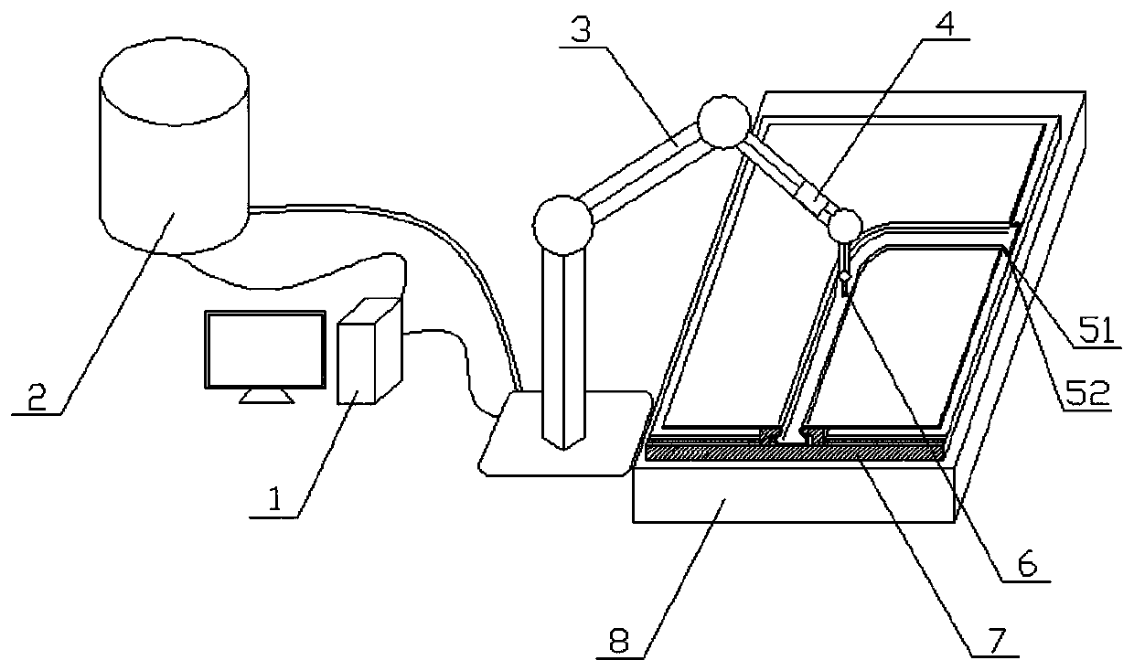
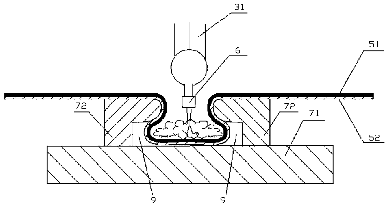
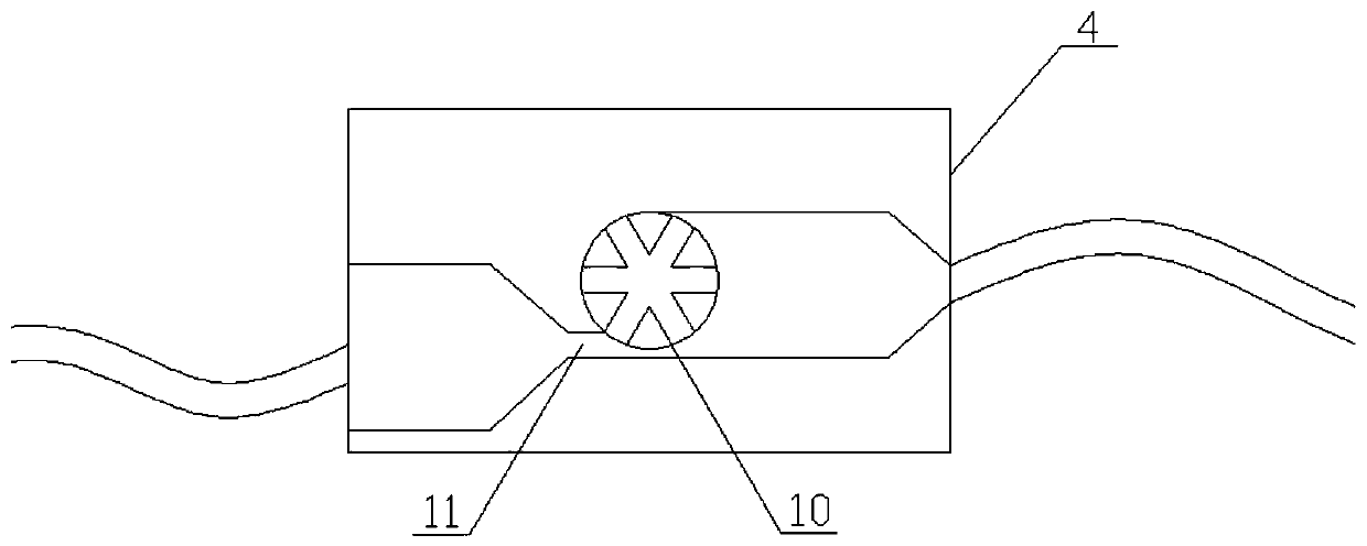
[0047] Such as Figure 1-3 As shown, a pulsating high-speed jet impact plate connecting device includes a control system 1, a high-pressure water pump 2, a joint robot 3, a pulsating loading device 4, a nozzle 6, a mold 7, a workbench 8 and a forming cavity 9.

[0048] The control system 1, the high-pressure water pump 2, and the articulated robot 3 are connected sequentially. The pulsation loading device 4 is installed in the articulated robot 3 and is close to the working end 31. The high-pressure water pump 2 is connected to a water source. At the same time, the control system 1 is connected to the articulated robot 3, the working end 31 of the articulated robot 3 communicates with the nozzle 6, and the control system 1 controls the trajectory and angle of the nozzle by controlling the working end of the articulated robot.

[0049] The pulsating loading device includes an impeller 10 and a water spray pipe 11. The water spray pipe 11 is aligned with the blades of the impell...

Embodiment 2

[0052] The method for connecting plates using the pulsating high-speed jet impacting plate connecting device described in Example 1 comprises the following steps:

[0053] (1) The mold 7 is fixed on the workbench 8, and the upper plate 51 and the lower plate 52 to be connected, wherein the material of the upper plate and the lower plate are SS304 stainless steel with a thickness of 0.15mm, are superimposed and placed on the mold 7 on two L-shaped brackets;

[0054] (2) Set the clamping angle and motion track of the joint at the working end 31 of the joint robot 3, so that the high-speed jet nozzle 6 can move the upper plate 51 and the lower plate 52 relative to each other according to the set angle and track.

[0055] (3) Set the pressure of the initial flow of water produced by the high-pressure pump 2 through the control system 1. The greater the thickness of the plate, the greater the initial flow pressure required, and then the pressure in the high-pressure water pump is s...

Embodiment 3

[0060] The method for connecting plates using the pulsating high-speed jet impacting plate connecting device described in Example 1 comprises the following steps:

[0061] (1) The mold 7 is fixed on the workbench 8, and the upper plate 51 and the lower plate 52 to be connected, wherein the material of the upper plate and the lower plate are SS304 stainless steel with a thickness of 0.2 mm, are placed on the mold 7 after being stacked together. on two L-shaped brackets;

[0062] (2) Set the clamping angle and motion track of the joint at the working end 31 of the joint robot 3, so that the high-speed jet nozzle 6 can move the upper plate 51 and the lower plate 52 relative to each other according to the set angle and track.

[0063] (3) Set the pressure of the initial flow of water produced by the high-pressure pump 2 through the control system 1. The greater the thickness of the plate, the greater the initial flow pressure required, and then the pressure in the high-pressure wa...


PUM


Abstract

The invention relates to an impulse high-speed jet impacting board material connecting device, and belongs to the technical field of thin board connection. The device comprises a control system, a high-pressure water pump, an impulse loading device, a joint robot, a spraying nozzle, a mold, a workbench and a forming cavity; the control system, the high-pressure water pump and the joint robot are successively connected, the impulse loading device is installed in the joint robot, and the high-pressure water pump is communicated with a water source at the position close to the work end of the joint robot; the control system is connected with the joint robot, the work end of the joint robot is communicated with the spraying nozzle, and the control system controls the work end of the joint robot to control the motion trace and angle of the spaying nozzle; a forming mold is installed on the workbench. Impulse high-speed jet flow can significantly improve the forming capacity of board materials, friction force generated in the forming process is reduced, and therefore distribution of the thickness of a deformed part is more uniform.

Description

technical field [0001] The invention relates to the technical field of thin plate connection, in particular to a plate connection method and device based on pulsating high-speed jet impact. Background technique [0002] Material connection technology is one of the widely used technologies in the field of mechanical manufacturing. According to the basic principle of connection realization, it can be divided into mechanical connection and physical and chemical connection. Common mechanical connection methods include bolt connection, screw connection, rivet connection, key connection, pin connection, etc. Common physical and chemical connection methods include adhesive bonding, welding, sealing, etc. The difference between mechanical connection and physical and chemical connection lies in the realization of the connection. Whether changes in physical state (such as solid-liquid phase transition) and chemical properties occur in the main process. Each of these connection techno...

Claims


Application Information

Patent Timeline
Patent Type & Authority Patents(China)
IPC IPC(8): B23K28/00B23K20/00
CPCB23K20/00B23K28/00
Inventor 季忠苏蕴琪刘韧郑超
Owner SHANDONG UNIV
Learn More