

Rock breaking device
a technology of rock breaking device and percussion, which is applied in the direction of manufacturing tools, portable percussive tools, construction, etc., can solve the problems of increasing the mounting and design complexity of the rock breaking device, complicated solution to incorporate into the body of the device, and causing damag
Active Publication Date: 2018-12-06
MONTABERT SA
View PDF6 Cites 1 Cited by
- Summary
- Abstract
- Description
- Claims
- Application Information
AI Technical Summary
Benefits of technology
The invention allows for controlling the flow rate of fluid between two circuits by using the movement of an impact piston. This helps to reduce the size and complexity of the rock breaking device. It also makes it easier to integrate and mount the protection against excess flow rates with existing elements. Additionally, the invention includes a braking system that calibrates the amount of fluid transmitted between the two circuits, while also reducing the size of the braking system.
Problems solved by technology
Furthermore, damage may also appear due to this overspeed.
However, this solution is complicated to incorporate into the body of the device.
However, this solution requires modifying the carrier machine.
The increase in the bulk of the power cell 120 also increases the mounting and design complexity of the rock breaking device.
Furthermore, this solution is not implemented for low-power devices, since the bulk of the solution for protecting against excess flow rates would be too great compared to the volume of the power cell 120.
Method used
View moreImage
Smart ImageViewing Examples

Examples
first embodiment
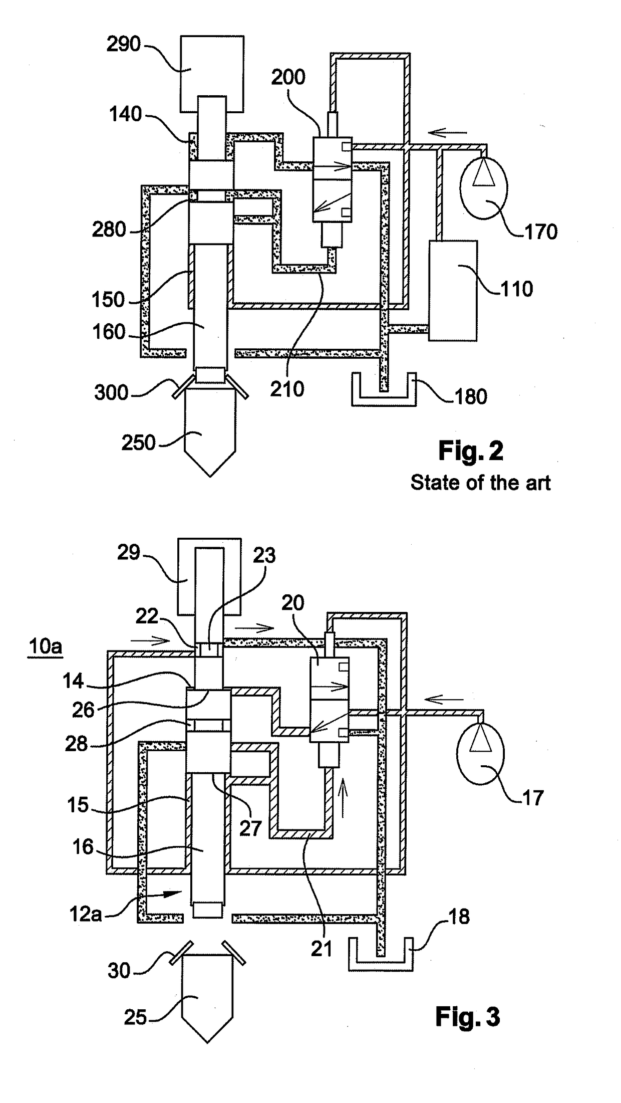
[0056]FIG. 3: a schematic representation in cross-section of a rock breaking device according to the invention;
second embodiment
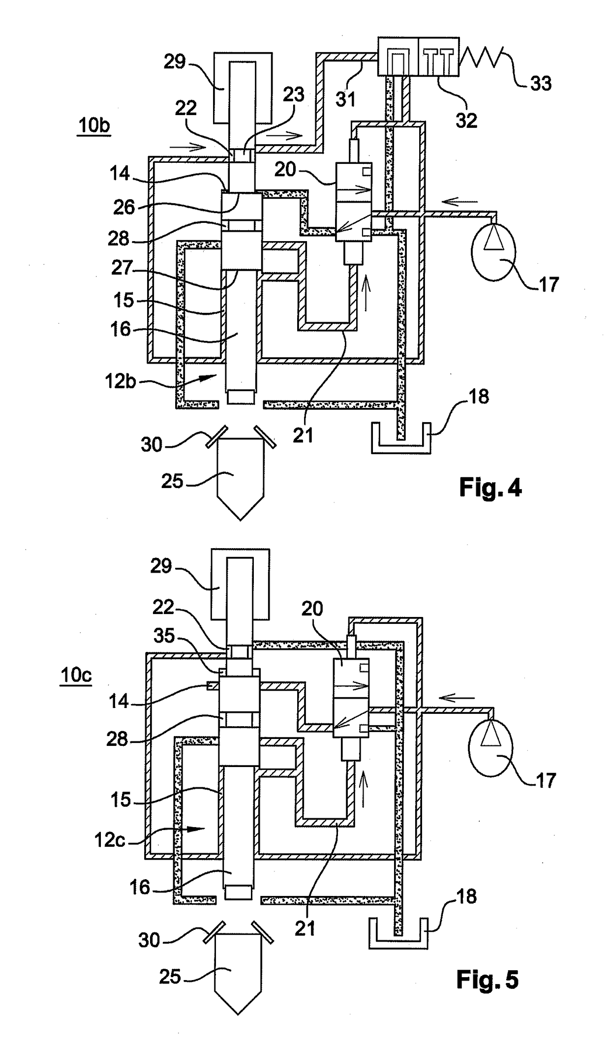
[0057]FIG. 4: a schematic representation in cross-section of a rock breaking device according to the invention;
third embodiment
[0058]FIG. 5: a schematic representation in cross-section of a rock breaking device according to the invention;
Login to View More PUM
 Abstract
The invention concerns a rock breaking device comprising a striking cell having at least one actuation chamber, a striking piston, and a hydraulic circuit comprising a hydraulic supply source having a High Pressure circuit and a Low Pressure circuit, and an actuator configured to connect the High Pressure circuit or the Low Pressure circuit to the actuation chamber so as to move the piston in translation in the striking cell in a normal movement area of which the limits are variable depending on the pressure difference between the High Pressure circuit and the Low Pressure circuit, the striking cell comprising depressurizing means configured to control the establishment of hydraulic communication between the High Pressure circuit and the Low Pressure circuit when the striking piston exits a predefined movement area.
Description
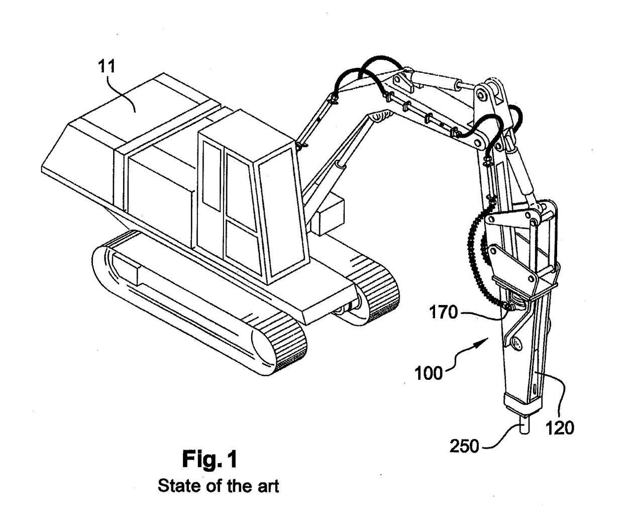
TECHNICAL FIELD[0001]The present invention relates to the domain of construction machinery. It concerns a hydraulic percussion device of the “rock breaker” or similar type.PRIOR ART[0002]As described in FIGS. 1 and 2 illustrating the state of the art, hydraulic percussion devices 100 called “rock breakers” are generally made up of a body containing a power cell 120 protected from the outside environment by a mechanically welded structure that also makes it possible to fasten the power cell 120 to a carrier machine 11.[0003]The power cell 120 comprises a greased mechanical front part that bears a tool 250 intended to come into contact with a rock to be broken. The tool 250 is guided by wearing rings, retained in translation in one direction by a system of keys and in the other by a press-fitting stop 300 that makes it possible to transmit the impact from the carrier machine 11. A central part of the power cell 120 comprises an impact piston 160 translatable within a cylinder in such ...
Claims
Login to View More Application Information
Patent Timeline
 Patent Type & Authority Applications(United States)
IPC IPC(8): B25D17/24B25D9/12B25D9/18B25D9/26
CPCB25D17/245B25D9/12B25D9/18B25D9/26B25D2217/0023B25D2250/195E02F3/966E02F9/2221E02F9/2271
Inventor PIRAS, BERNARD
Owner MONTABERT SA