
Contactor device integrating pyrotechnic disconnect features

a technology of contactor device and pyrotechnic disconnect, which is applied in the direction of protective switch operation/release mechanism, protective switch details, relay, etc., can solve the problems of permanent circuit breakage, requiring precious additional space to accommodate the plurality of devices,

Active Publication Date: 2018-12-06
GIGAVAC INC
View PDF1 Cites 10 Cited by
  • Summary
  • Abstract
  • Description
  • Claims
  • Application Information

AI Technical Summary

Benefits of technology

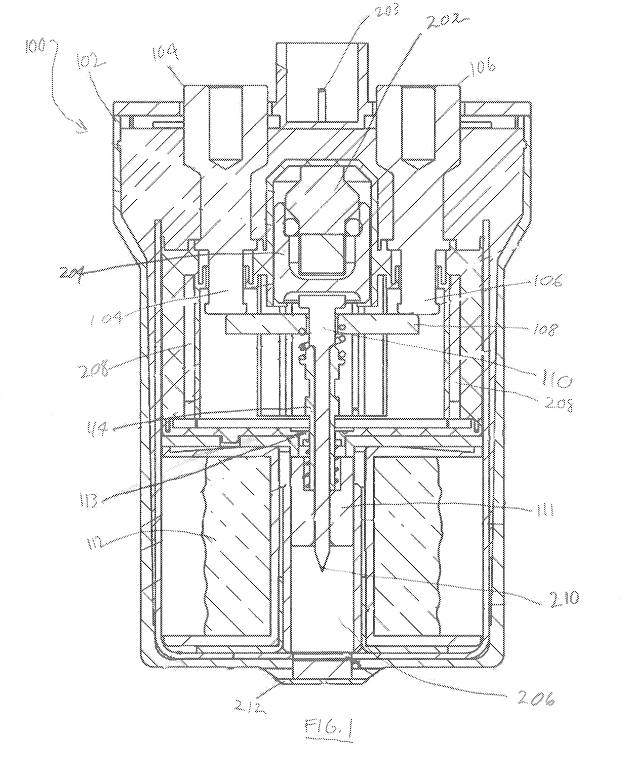
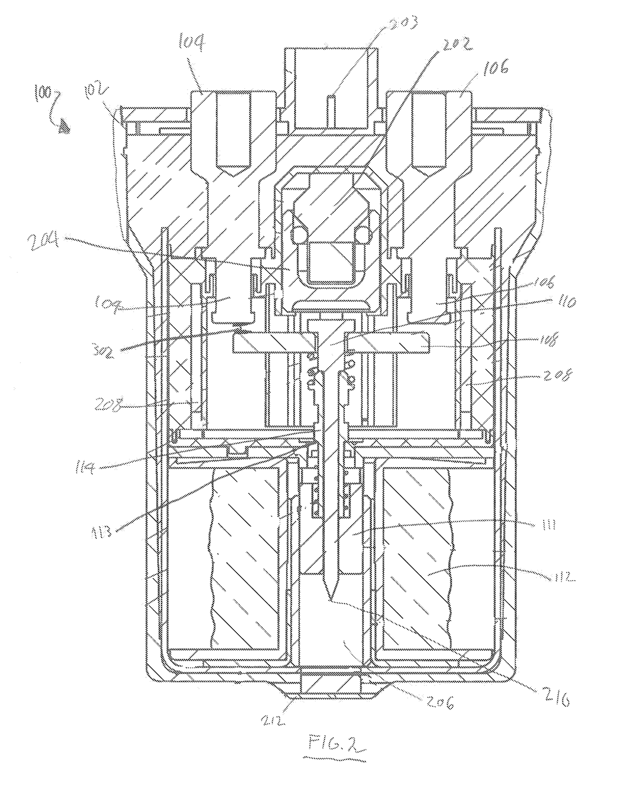
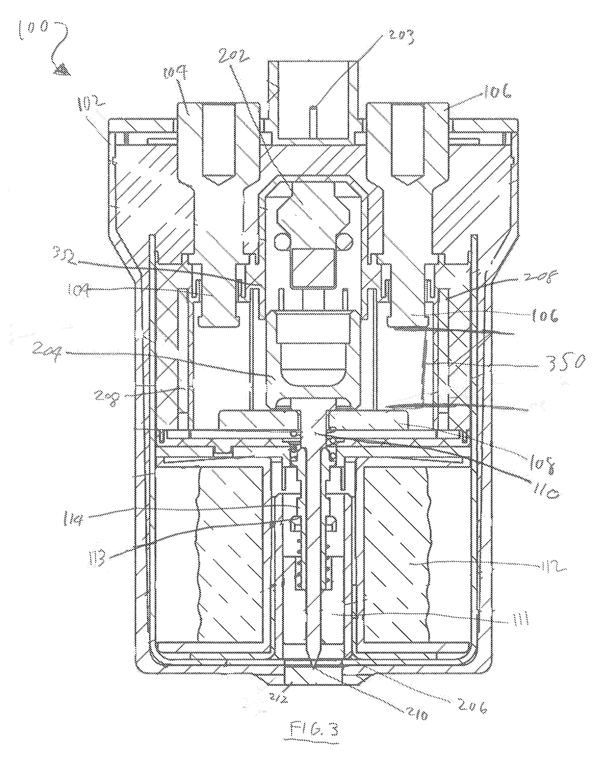
The patent describes contactors that can interrupt or complete a circuit, and also have a feature that can permanently break the circuit. This feature is called a disconnect element, which is designed to protect against overcurrent situations. The contactor devices described have a housing and include internal components that can change the state of the device to open or close it. The devices also have fixed and moveable contacts, a shaft structure, and pyrotechnic features that can activate and interact with the shaft structure to cause a change in its configuration. This results in the separation of the moveable contacts from the fixed contacts. The technical effects of this invention are that it provides improved overcurrent protection and enables the permanent breaking of a circuit.

Problems solved by technology

One issue in utilizing conventional contactors and disconnect devices is that if a circuit design requires both a contactor and a disconnect device, for example, to provide both a switch for ordinary operation and an overcurrent protection element, at least two separate devices must be utilized.
Especially in expensive modern electrical devices, such as electric cars, this requires precious additional space to accommodate the plurality of devices, as well as necessitating additional design considerations to connect a plurality of devices in circuit to the electrical device.
When these pyrotechnic features are activated, the resulting explosion generates sufficient force to cause movement or change in orientation between internal features in the contactor, resulting in a permanent circuit break.

Method used


Image

  • Contactor device integrating pyrotechnic disconnect features
  • Contactor device integrating pyrotechnic disconnect features
  • Contactor device integrating pyrotechnic disconnect features

Examples


Embodiment Construction

[0016]The present disclosure will now set forth detailed descriptions of various embodiments. These embodiments set forth contactor devices comprising a housing containing internal components configured to change the state of the device between a state that allows for electricity to flow through the device and a state that does not allow electricity to flow through the device and vice versa.

[0017]The change between these two states can be in response to various forms of input that can be received, for example, manual input such as a user pressing a button to perform a “switching” function utilizing the contactor device. Other forms of input can include automated input, for example, sensors or a set of computer commands stored in non-transient medium executed by a processor that will cause the internal components to transition between states in response to timing information or system information detected by sensors in communication with the disconnect device, for example, current, v...


PUM


Abstract

Disclosed herein are contactor devices, for example, devices that can be utilized as switching elements, comprising fixed contacts that are electrically isolated from one another and one or more moveable contacts that are configured to electrically contact the fixed contacts to provide an electrical connection between them. Movement of the fixed contacts into and out of electrical contact with the fixed contacts controls flow of electricity through the devices. The contactor devices also include pyrotechnic disconnect elements, which function as a circuit break or fuse-like element to protect against overcurrent. When the electrical current through the contactor device reaches a threshold level, a pyrotechnic charge activates, permanently forcing the moveable contacts out of electrical contact with the fixed contacts.

Description

CROSS REFERENCE TO RELATED APPLICATIONS[0001]This application is a continuation-in-part of, and claims the benefit of, U.S. application Ser. No. 15 / 889,516 to Murray Stephan McTigue, et al., entitled Mechanical Fuse Device, filed on Feb. 6, 2018, which in turn is a continuation-in-part of, and claims the benefit of, U.S. application Ser. No. 15 / 146,300 to Murray Stephan McTique, et al., entitled Mechanical Fuse Device, filed on May 4, 2016, which in turn claims the benefit of U.S. Provisional Application Ser. No. 62 / 163,257 to Murray S. McTigue, et al., entitled Mechanical Fuse Device, filed on May 18, 2015. U.S. application Ser. No. 15 / 889,516, and the present application, both further claims the benefit of U.S. Provisional Application 62 / 612,988 to Daniel Sullivan, et al., entitled Contactor Device Integrating Pyrotechnic Disconnect, filed on Jan. 2, 2018. Each of these applications are hereby incorporated herein in their entirety by reference.BACKGROUNDField of the Invention[0002...

Claims


Application Information

Patent Timeline
Patent Type & Authority Applications(United States)
IPC IPC(8): H01H39/00H01H89/00H01H71/02H01H71/10H01H50/54H01H50/18
CPCH01H50/54H01H50/18H01H33/18H01H2223/002H01H39/00H01H89/00H01H71/02H01H71/10H01H9/443H01H1/20H01H2039/008H01H50/20H01H50/546H01H85/041H01H85/143H01H85/165H01H71/2472H01H77/06
Inventor SULLIVAN, DANIELMCTIGUE, MURRAY STEPHANMOLYNEUX, MICHAEL HENRY
Owner GIGAVAC INC
Learn More