

Mobile curing system using superheated air
a technology of superheated air and curing system, which is applied in the direction of mechanical equipment, soil-shifting machines/dredgers, other domestic objects, etc., can solve the problems of difficult to ascertain the extent of deterioration, the infrastructure of the nation such as roads, bridges and underwater pipes is aging, and the infrastructure is often critically deteriorated
- Summary
- Abstract
- Description
- Claims
- Application Information
AI Technical Summary
Benefits of technology
Problems solved by technology
Method used
Image

Examples
Embodiment Construction
[0019]The following detailed description is of the best currently contemplated modes of carrying out exemplary embodiments of the invention. The description is not to be taken in a limiting sense, but is made merely for the purpose of illustrating the general principles of the invention, since the scope of the invention is best defined by the appended claims.
[0020]The following structure numbers shall apply to the following structures among the various FIGS.:
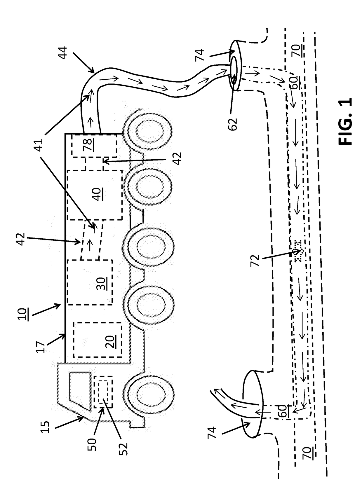
[0021]10—Curing system;
[0022]15—Truck;
[0023]17—Enclosure;
[0024]20—Generator;
[0025]30—Blower;
[0026]40—Heater
[0027]41—Air;
[0028]42—Heater intake;
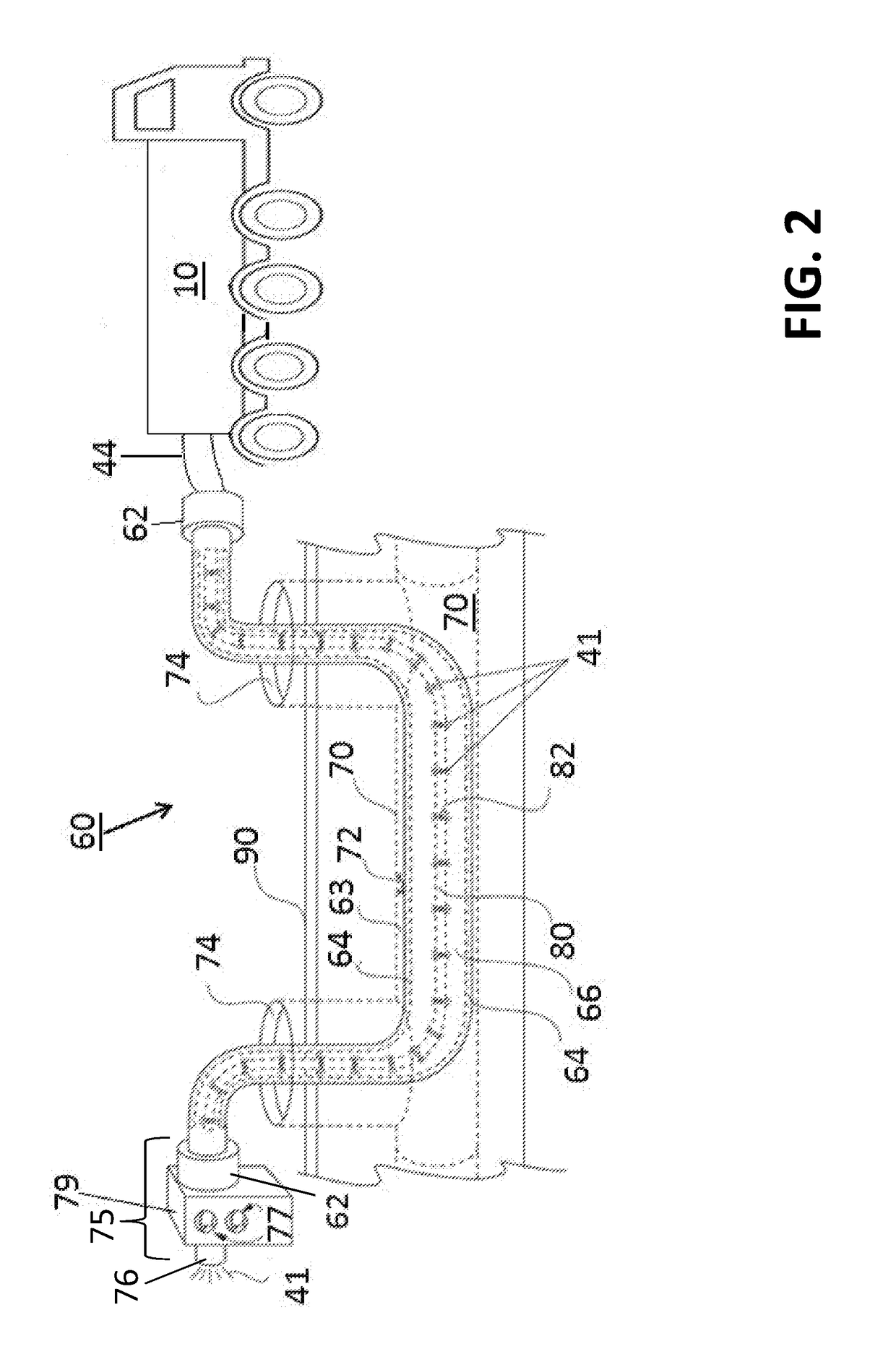
[0029]44—Heater output;
[0030]45—Hot air inlet;
[0031]46—Pressure feedback outlet;
[0032]47—Pressure feedback return;
[0033]48—Hot air outlet;
[0034]50—Control system;
[0035]52—Display;
[0036]60—Lining system;
[0037]62—End cap;
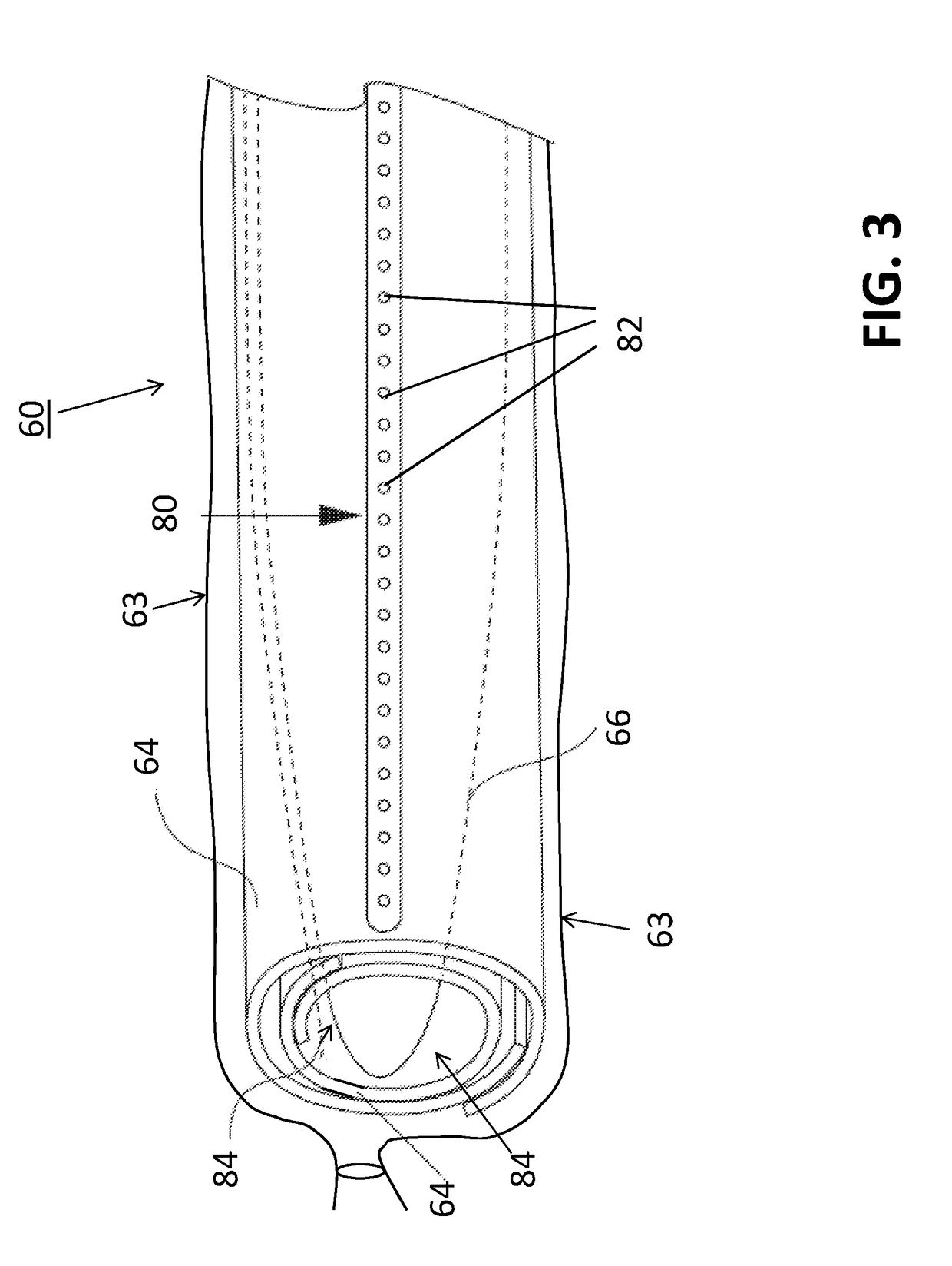
[0038]63—Film;
[0039]64—Tubular substrate;
[0040]66—Bladder;
[0041]67—Double wall;
[0042]68—Ratcheting strap;
[0043]69—Retaining ridge;
[0044]70—Pipe;
[0045]72—Compromised portion...
PUM
| Property | Measurement | Unit |
|---|---|---|
| temperature | aaaaa | aaaaa |
| power | aaaaa | aaaaa |
| pressure | aaaaa | aaaaa |
Abstract
Description
Claims
Application Information