Motor drive apparatus and motor drive method

a motor drive and motor technology, applied in the direction of electronic commutators, program control, instruments, etc., can solve the problems of not being able to prevent the voltage from being increased, brushless motors may be stopped, and it is not possible to adjust the advanced angl

Active Publication Date: 2018-12-13
MITSUBA CORP
View PDF0 Cites 3 Cited by
  • Summary
  • Abstract
  • Description
  • Claims
  • Application Information

AI Technical Summary

Benefits of technology

[0017]As described above, according to an aspect of the present invention, it is possible to provide a motor drive apparatu

Problems solved by technology

Therefore, the motor drive apparatus may recognize the voltage increase due to the counter electromotive voltage as an abnormal voltage increase occurring and may stop driving the brushless motor for the purpose of protecting an erroneous operation or the failure of circuit components.
In this case, it is not possible to prevent the voltage from being increased even when performing the non-free rectangular wave drive described above, and th

Method used


Image

  • Motor drive apparatus and motor drive method
  • Motor drive apparatus and motor drive method
  • Motor drive apparatus and motor drive method

Examples


Embodiment Construction

[0024]Hereinafter, an aspect of the present invention is described according to an embodiment of the invention, but the following embodiment does not limit the invention according to claims. Further, all of the combinations of features described in the embodiment are not necessarily indispensable for solving the problem addressed by the invention. In the drawings, the same reference numerals may be given to the same or similar parts, and redundant descriptions may be omitted. The shape, size, and the like of an element in the drawing may be exaggerated for clear description.

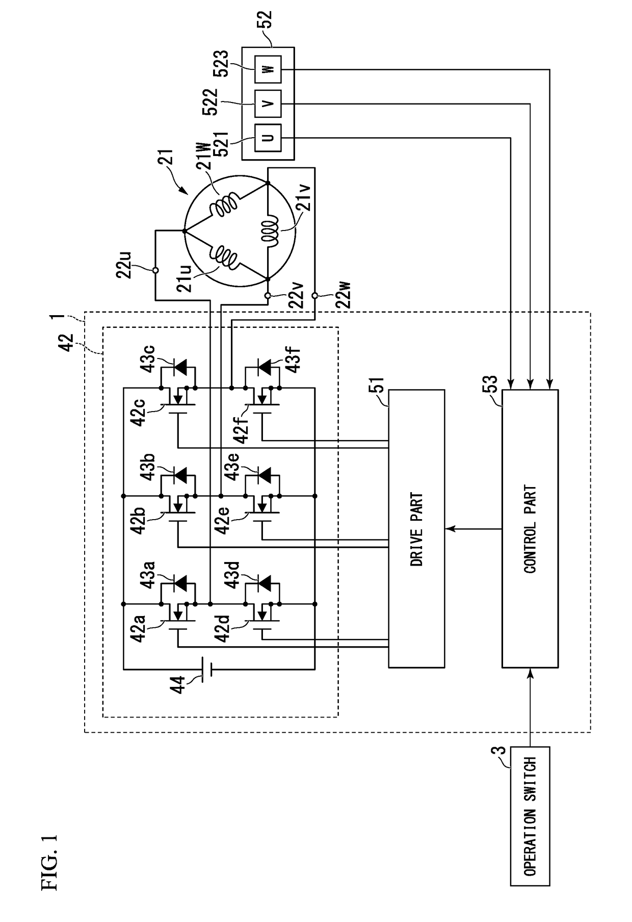
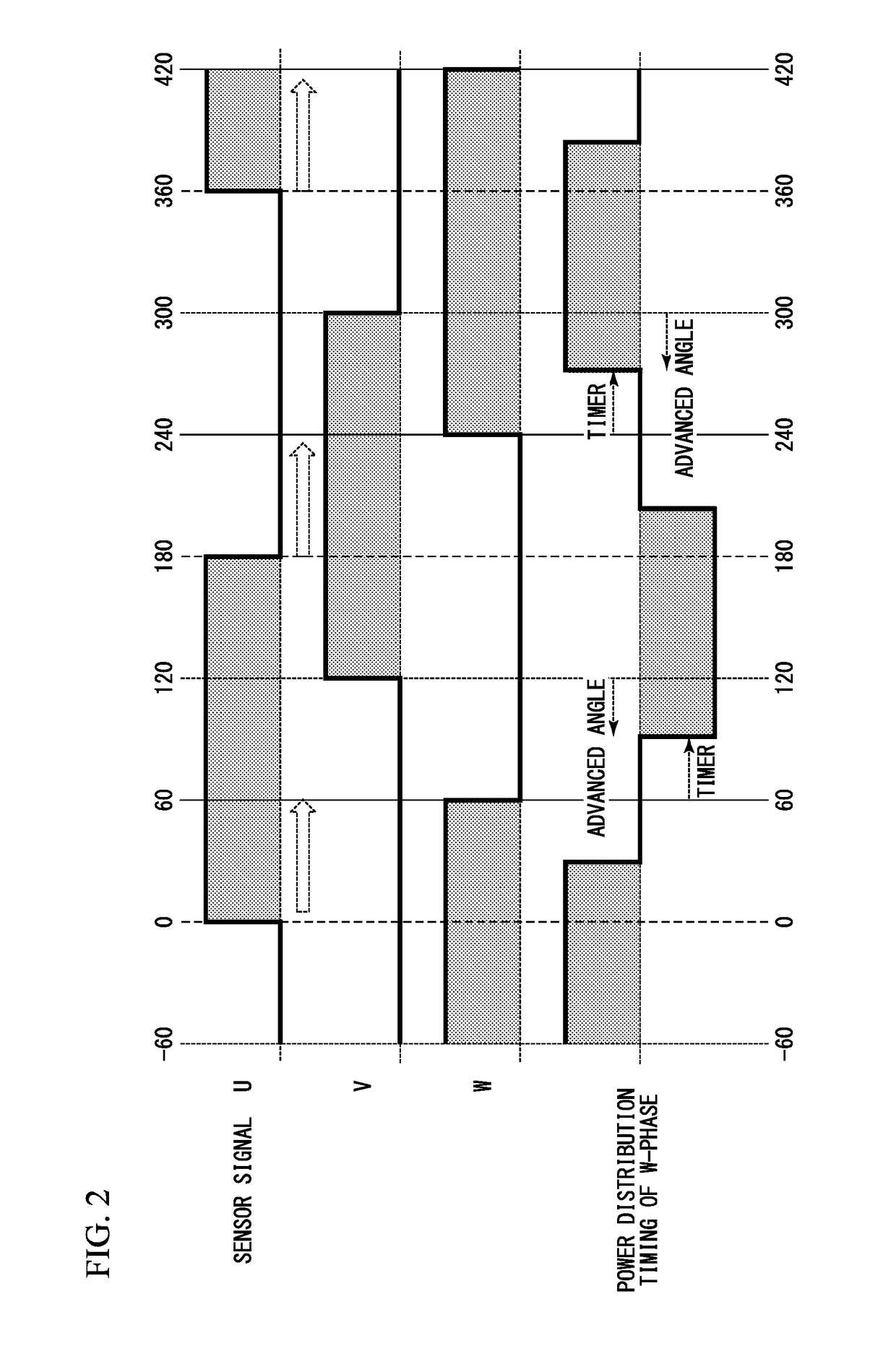
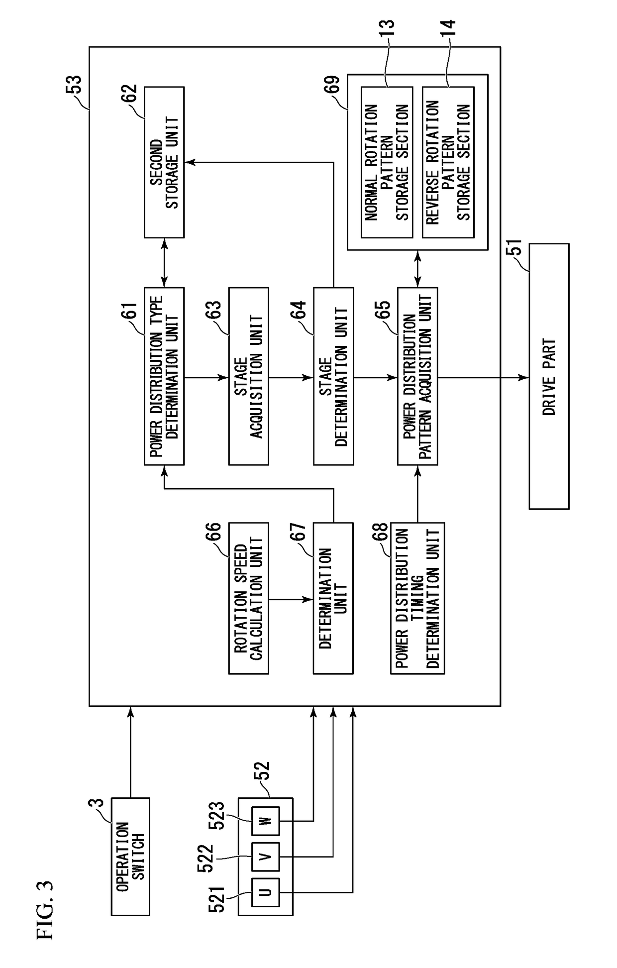
[0025]A motor drive apparatus in an embodiment supplies a current to a plurality of coils and rotates a rotor. The motor drive apparatus includes: a plurality of detection sensors that are provided at a phase different from each other in a rotation direction of the rotor and that detect a phase in a rotation direction of the rotor and generate an output signal; a stage determination part that determines a positio...


PUM


Abstract

A motor drive apparatus includes: a stage determination part that determines a position of the rotor based on a combination of states of a plurality of the output signals; and a power distribution timing determination part which determines that a power distribution timing when power is distributed to the coil is a timing obtained by advancing an angle by an amount that corresponds to a predetermined electric angle in a startup time of the motor, wherein, when a rotation speed of the motor becomes a predetermined rotation speed or more, the power distribution timing determination part determines that a timing when a predetermined period of time elapses since a position of the rotor arrives at a position of an electric angle that corresponds to a displacement amount of an electric angle which is arbitrarily advanced with respect to a predetermined electric angle that is advanced in the startup time is a power distribution timing.

Description

TECHNICAL FIELD[0001]The present invention relates to a motor drive apparatus and a motor drive method.[0002]Priority is claimed on Japanese Patent Application No. 2016-020157 filed on Feb. 4, 2016, the contents of which are incorporated herein by reference.BACKGROUND[0003]In the related art, when driving a brushless motor, a motor drive apparatus sets a mechanical advanced angle to 0 degrees, changes the advanced angle on a software, and drives the brushless motor. Specifically, the motor drive apparatus acquires a sensor signal that corresponds to each of a U-phase, a V-phase, and a W-phase of the brushless motor from a detection sensor (for example, a Hall IC) that detects a rotation position of a motor.[0004]Then, the motor drive apparatus recognizes a stage number on the basis of the acquired sensor signal, reads out a power distribution pattern that corresponds to the stage number, performs shifting by a predetermined rotation position (for example, an electric angle of 30 deg...

Claims


Application Information

Patent Timeline
IPC IPC(8): H02P6/15
CPCH02P6/153H02P2203/03H02P6/20G05B19/4015
Inventor KOJIMA, NAOKIKOBAYASHI, TOMOFUMIKAWASAKI, ATSUSHI
Owner MITSUBA CORP
Why Eureka
Try Eureka