
Circuit assembly for a switchable line termination of a serial bus

a serial bus and circuit assembly technology, applied in the field of circuit assembly for switchable line termination of serial bus, can solve the problems of inflexible and disadvantageous, and the function cannot be guaranteed withou

Active Publication Date: 2018-12-20
KNORR-BREMSE SYST FUER NUTZFAHRZEUGE GMBH
View PDF3 Cites 3 Cited by
  • Summary
  • Abstract
  • Description
  • Claims
  • Application Information

AI Technical Summary

Benefits of technology

The invention provides an electronic circuit for a switchable line termination of a serial bus that does not change the data of the bus and ensures proper communication without affecting the overall function of the circuit. The advantages of the invention include programmability of different resistance values, variable bus termination for optimal performance based on vehicle and geometrical conditions, better data transmission quality, and cessation of mismatches with the bus lines.

Problems solved by technology

Arrangements which can comprise terminating resistors which can be connected manually, for example, by wire bridges, bridges in a cable harness and the like are inflexible and disadvantageous in so far as changes to the characteristic data of a bus cannot be excluded and a function cannot be ensured without any influence on the bus communication.

Method used


Image

  • Circuit assembly for a switchable line termination of a serial bus
  • Circuit assembly for a switchable line termination of a serial bus

Examples


Embodiment Construction

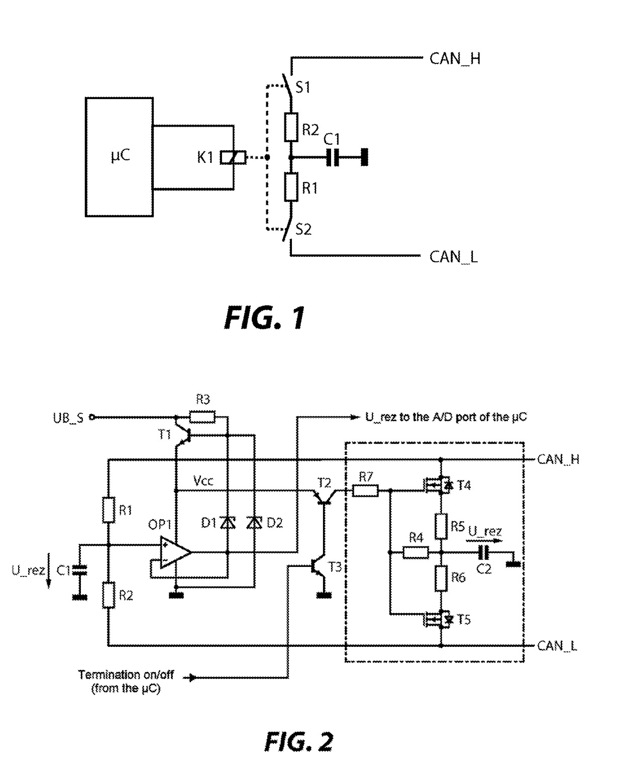
[0029]It is noted that equivalent or identically acting elements can have the same reference symbols or at least similar reference symbols in the drawing and are each not described again in this case.

[0030]FIG. 1 shows a schematic illustration of an underlying basic configuration of a circuit arrangement for a switchable line termination of a serial bus according to the invention.

[0031]According to FIG. 1, a microcontroller μC or predetermined ports of the latter is / are connected, via input / output lines or control lines, to a circuit arrangement K which, in the present exemplary embodiment, forms a circuit arrangement for a switchable line termination of a serial bus. The circuit arrangement K comprises termination or (line) terminating resistors for the serial bus and is arranged to connect or disconnect these termination or terminating resistors to / from signal lines CAN_H, CAN_L of the serial bus by electronic switching devices or switches S1, S2 on a case-by-case basis.

[0032]A fi...


PUM


Abstract

An electronic circuit arrangement, by which a line termination or terminating resistor of a serial bus, for example a CAN bus, is implemented in a switchable manner and can be electronically connected or disconnected by electronically operating switching elements and a microcontroller, or a computer port of the latter, which is present in an electronic control unit.

Description

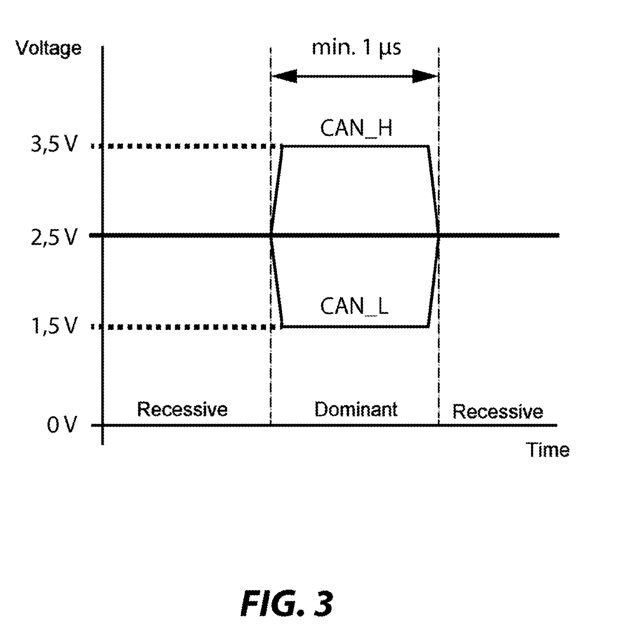
FIELD OF THE INVENTION[0001]The present invention relates to a circuit arrangement for a switchable line termination of a serial bus and relates, in particular, to a circuit arrangement for electronically connecting and / or disconnecting a termination to / from a CAN bus.BACKGROUND INFORMATION[0002]Serial bus arrangements such as CAN (Controller Area Network), FlexRay and the like are widespread in various technical fields, for example automotive engineering, for the purpose of networking control units. The CAN bus operates, for example, according to the so-called multi-master principle and connects a plurality of control units having equal rights. A CSMA / CR method resolves collisions, that is to say simultaneous bus access operations, without damaging the winning, higher-priority message. For this purpose, the bits are dominant or recessive (a dominant bit overwrites a recessive bit), depending on the state. In this case, the logic 1 is recessive (wired AND). The bus can be physically...

Claims


Application Information

Patent Timeline
Patent Type & Authority Applications(United States)
IPC IPC(8): H04L25/02G06F13/40H04L12/40
CPCH04L25/0278G06F13/4086H04L25/0298H04L12/40032H04L2012/40215
Inventor GSCHEIDLE, WOLFGANG
Owner KNORR-BREMSE SYST FUER NUTZFAHRZEUGE GMBH
Learn More