

Vehicle lower section structure
a lower section and vehicle technology, applied in the field of vehicle lower section structure, can solve the problem of increasing the weight of the vehicle by the reinforcement structure, and achieve the effect of reducing the weight of the vehicle and ensuring the stability of the vehicl
- Summary
- Abstract
- Description
- Claims
- Application Information
AI Technical Summary
Benefits of technology
Problems solved by technology
Method used
Image

Examples
Embodiment Construction
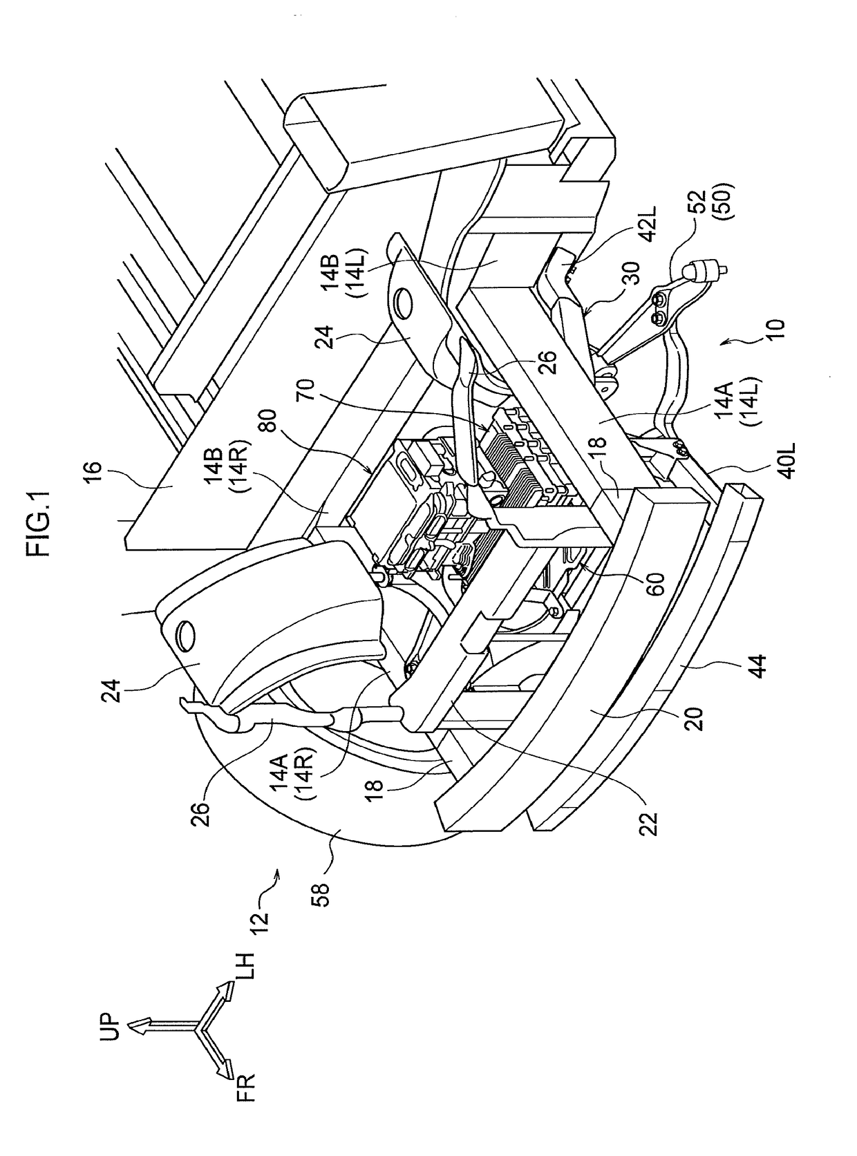
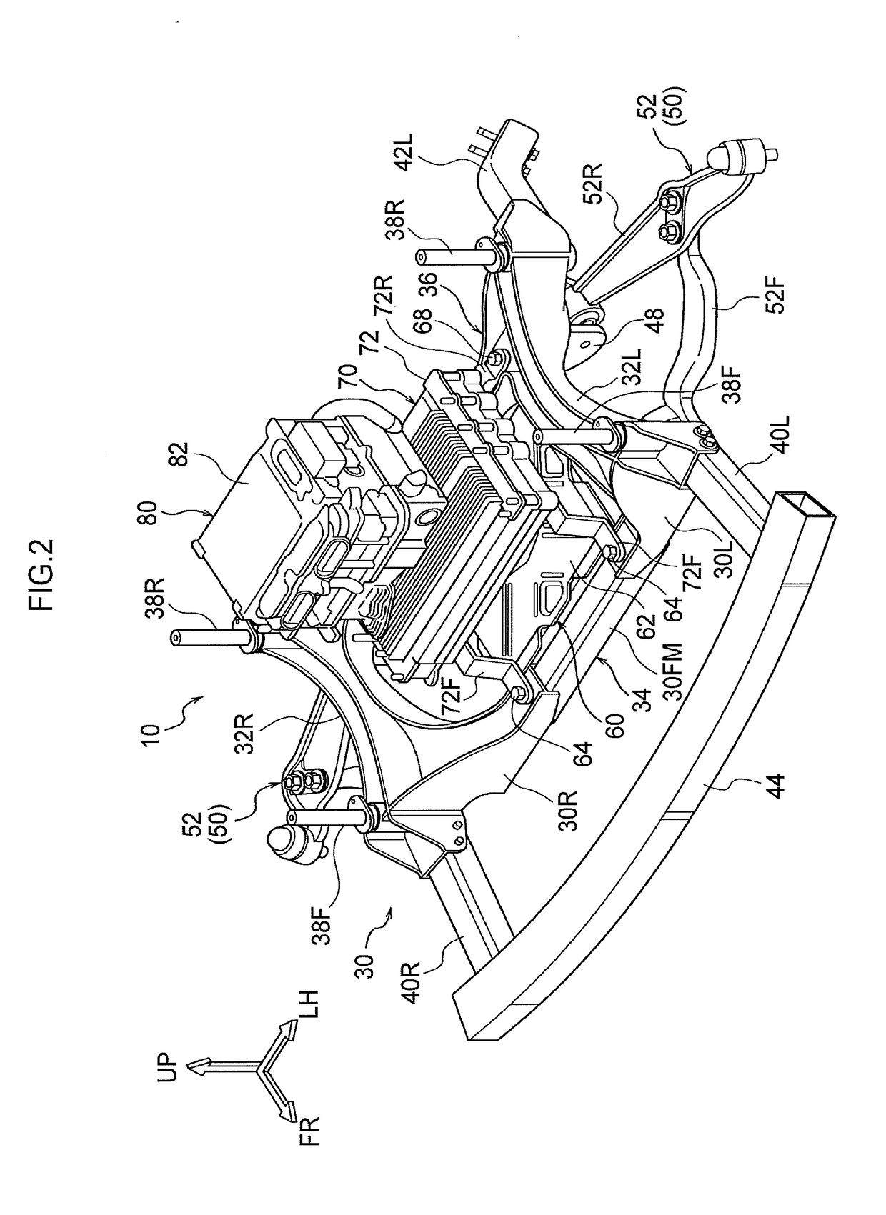
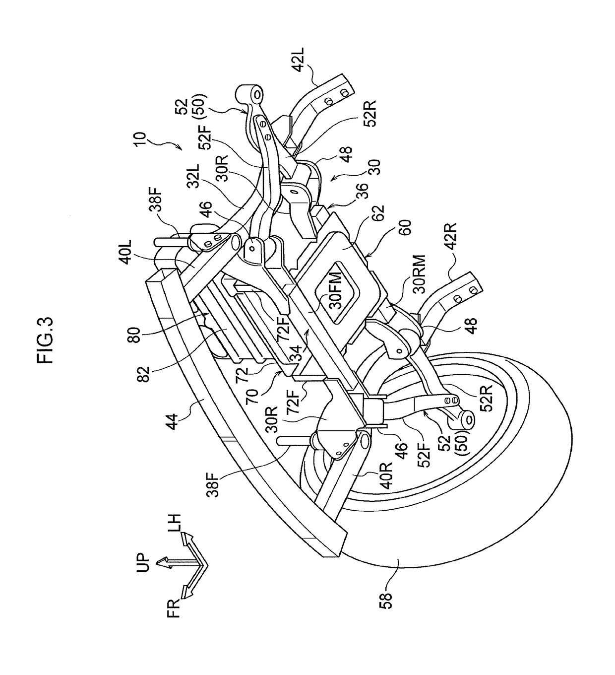
[0026]Explanation follows regarding a vehicle lower section structure 10 according to an exemplary embodiment of the present disclosure, with reference to FIG. 1 to FIG. 8. Note that the arrow FR, the arrow UP, and the arrow LH in the drawings respectively indicate the front direction (direction of travel), upper direction, and left direction of the vehicle, as appropriate. Hereafter, unless specifically stated otherwise, reference simply to the front and rear, left and right, and upward and downward directions refers to the front and rear in a vehicle front-rear direction, left and right in a vehicle left-right direction (vehicle width direction), and upward and downward in a vehicle vertical direction. Moreover, in the drawings, some reference numerals and some members may be omitted in order to aid understanding of the drawings.
[0027]As illustrated in FIG. 1 to FIG. 8, the vehicle lower section structure 10 according to the present exemplary embodiment includes a front suspension...
PUM
 Abstract
Description
Claims
Application Information