Front vehicle body structure

a front and body technology, applied in the direction of vehicle components, pivoted suspension arms, resilient suspensions, etc., can solve the problems of affecting the enhancement of productivity, difficult to achieve the same toe angle change between left and right wheels, and difficult to position mounting members such as fixing bushes in left-right symmetrical relation to one, etc., to achieve efficient transmission, efficient borne, and sufficient rigidity

Inactive Publication Date: 2011-07-12
HONDA MOTOR CO LTD
View PDF16 Cites 33 Cited by
  • Summary
  • Abstract
  • Description
  • Claims
  • Application Information

AI Technical Summary

Benefits of technology

[0006]It is therefore a first object of the present invention to provide an improved front vehicle body structure which can minimize a difference in toe angle change between left and right wheels caused by braking loads, and which can secure a sufficient rigidity of the front sub frame without increasing the number of necessary component parts.
[0007]In order to accomplish the above-mentioned object, the present invention provides an improved front vehicle body structure, which comprises: a front sub frame disposed under and fixed to left and right side frames, a steering gear box being mounted on the front sub frame to extend in a vehicle width direction; and at least three support portions provided in left-right symmetrical arrangement on the front sub frame, the steering gear box being mounted on the support portions via bushes.
[0008]Because the steering gear box is mounted on the support portions provided in left-right symmetrical relation to each other, loads applied from left and right lower arms of left and right suspensions to the front sub frame can be borne uniformly by the steering gear box. Thus, when loads are applied from the left and right suspensions to left and right tie rods, the left and right tie rods can be caused to move the same amount. As a result, the present invention can minimize a difference in toe angle change between left and right wheels caused by braking loads. Further, because the loads applied from the left and right lower arms to the front sub frame can be borne uniformly by the steering gear box, the steering gear box can function also as a reinforcing member. Thus, there is no need to provide a cross member as a separate reinforcing member, so that the present invention can secure a sufficient rigidity of the front sub frame without increasing the number of necessary component parts.
[0010]In a preferred form, the left and right lower arms of the left and right suspensions are connected to left and right lower-arm mounting portions, respectively, of the front sub frame, the left and right lower-arm mounting portions being located near where the front sub frame is fixed to the left and right side frames. In this way, the left and right lower-arm mounting portions can be reinforced with the left and right side frames, so that a sufficient rigidity of the left and right lower-arm mounting portions can be secured.
[0011]In an embodiment, the middle support portion is located at a substantial middle position, in a left-right direction, of the vehicle body, and the front vehicle body structure further includes a support member connected to the front sub frame to be located forwardly of the middle support portion for supporting a power source. Thus, a load applied from the support member to the front sub frame can be efficiently transmitted to the middle support portion. Because the steering gear box is mounted on the middle support portion, the load transmitted to the middle support portion can be efficiently borne by the steering gear box.

Problems solved by technology

However, because a steering gear pinion and electric assisting motor are provided on an end portion of one of left and right sides of the steering gear box, it is difficult to position the mounting members, such as the fixing bushes, in left-right symmetrical relation to one another.
Therefore, it has been considered difficult to achieve same toe angle changes between left and right wheels caused by braking loads.
The provision of the cross member on the front sub frame undesirably increases the number of necessary component parts, which would impede enhancement of productivity.

Method used


Image

  • Front vehicle body structure
  • Front vehicle body structure
  • Front vehicle body structure

Examples


Embodiment Construction

[0016]In the following description, the terms “front”, “rear”, “left” and “right” are used to refer to directions as viewed from a human operator or driver.

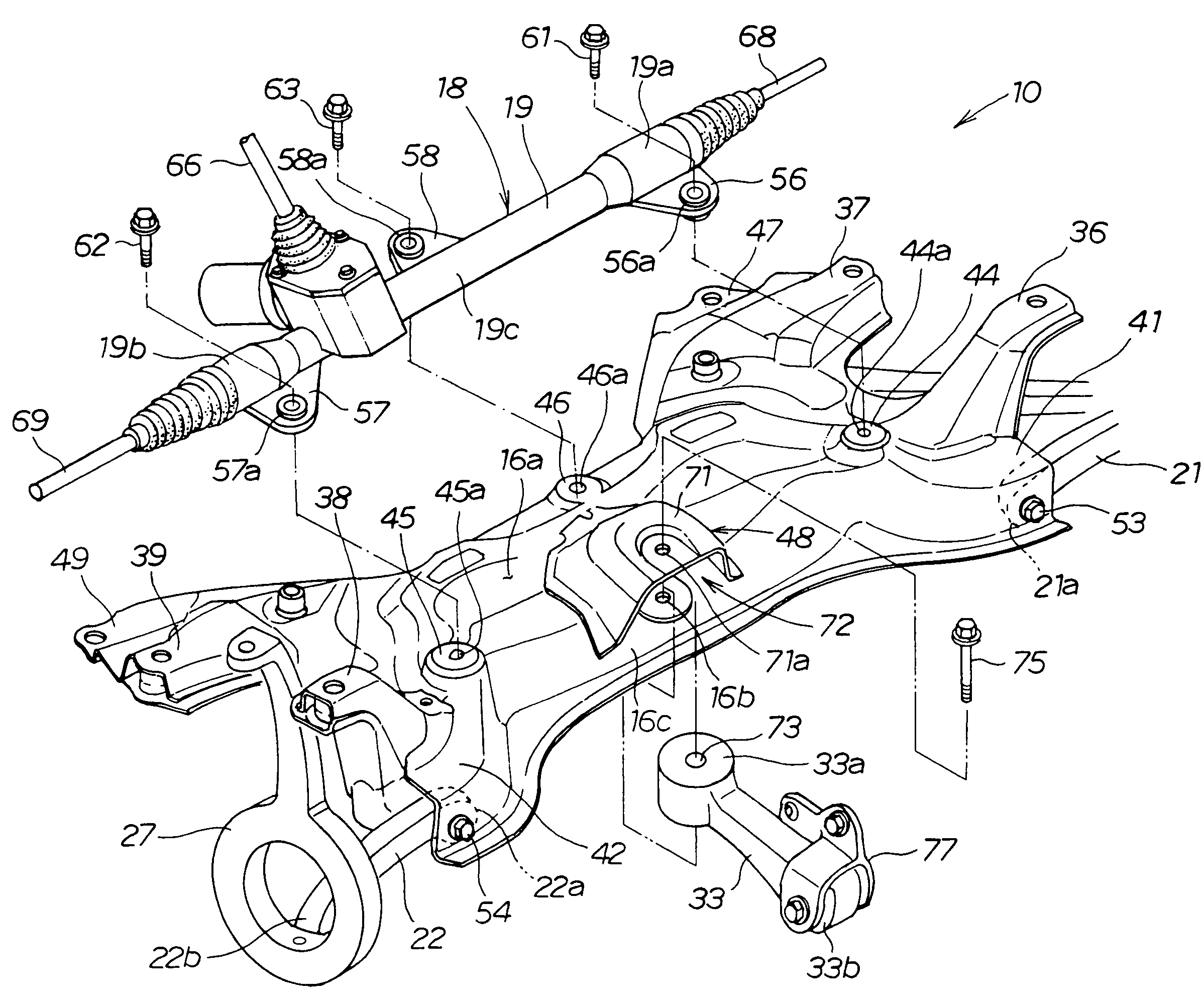
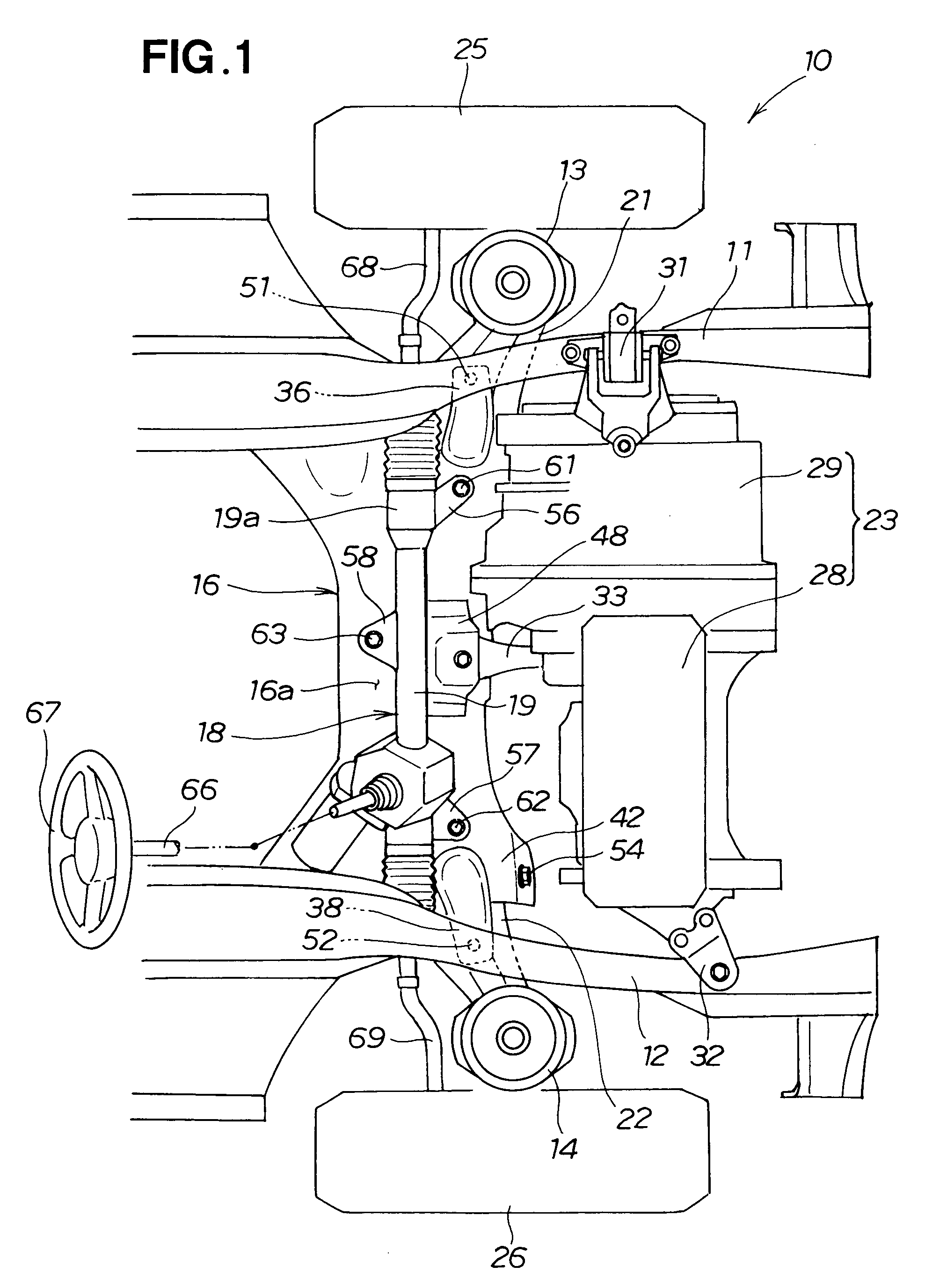
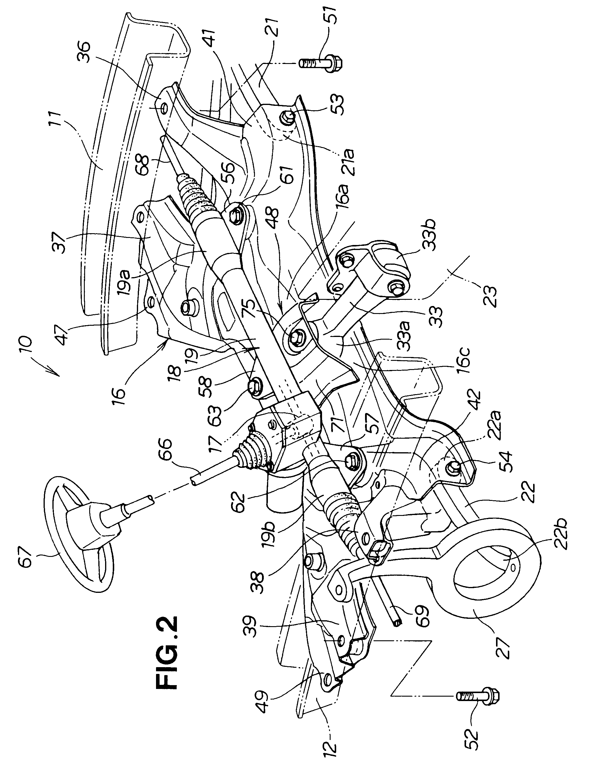
[0017]FIG. 1 is a plan view showing a front vehicle body structure 10 according to an embodiment of the present invention. The front vehicle body structure 10 includes: left and right side frames 11 and 12; a left suspension 13 disposed laterally outwardly of the left side frame 11; a right suspension 14 disposed laterally outwardly of the right side frame 12; a front sub frame 16 disposed under and fixedly connected to the left and right side frames 11 and 12; and a steering gear box 18 mounted on an upper portion 16a of the front sub frame 16.

[0018]Further, in the front vehicle body structure 10, a left lower arm 21 of the left suspension 13 is connected to a left end portion of the front sub frame 16, a right lower arm 22 of the right suspension 14 is connected to a right end portion of the front sub frame 16, and a power sour...


PUM


Abstract

Front vehicle body structure (10) includes a front sub frame (16) disposed under and fixedly connected to left and right side frames (11, 12), and a steering gear box (18) is mounted on the front sub frame to extend transversely along the width of the vehicle body. The body structure also has support portions (44, 45, 46) provided in left-right symmetrical arrangement on the front sub frame, and the steering gear box is mounted on the support portions via respective bushes.

Description

TECHNICAL FIELD[0001]The present invention relates to front vehicle body structures where a steering gear box is provided on a front sub frame disposed under left and right side frames.BACKGROUND ART[0002]Among the conventionally-known front vehicle body structures are ones where a front sub frame disposed under and fixedly connected to left and right side frames and front suspensions are attached to left and right end portions of the front sub frame. In such front vehicle body structures, a power source (engine) is disposed forwardly of the front sub frame, and the power source is connected, via a support member, to a substantial middle region of the front sub frame so that the power source is supported by the front sub frame (see, for example, Japanese Patent Application Laid-Open Publication No. 2000-238656). According to the front vehicle body structure disclosed in the 2000-238656 publication, when front wheels are braked during travel of the vehicle, loads are applied, in a wi...

Claims


Application Information

Patent Timeline
Patent Type & Authority Patents(United States)
IPC IPC(8): B62D21/11
CPCB62D21/11B62D3/12
Inventor YOSHIDA, HIROYUKIMACHIDA, TOMOMASAECHIGO, TAKAHIROSUZUKI, SHINYA
Owner HONDA MOTOR CO LTD
Why Eureka
Try Eureka