
Vehicle lower section structure

a lower section and vehicle technology, applied in the field of vehicle lower section structure, can solve the problem of increasing the weight of the vehicle by the reinforcement structure, and achieve the effect of reducing the weight of the vehicle and ensuring the stability of the vehicl

Active Publication Date: 2019-03-05
TOYOTA JIDOSHA KK
View PDF11 Cites 2 Cited by
  • Summary
  • Abstract
  • Description
  • Claims
  • Application Information

AI Technical Summary

Benefits of technology

The present patent provides a vehicle lower section structure that can efficiently reinforce its suspension system. Additionally, the patent also simplifies the fastening structures of the contactless charger and other electrical components, reducing the number of fastening processes and components, weight, and simplifying the vehicle's design. Additionally, the patent suggests that the cross member and the other electrical component can work together to bear lateral force in a vehicle turn, making it more effective. Overall, the patent provides a simplified and efficient solution for reinforcing the vehicle's suspension system and bearing lateral force during a turn.

Problems solved by technology

However, in the above disclosure, the reinforcement structure configured as a plate is attached to the sub-frame (suspension member), and thus the reinforcement structure increases the vehicle weight.

Method used


Image

  • Vehicle lower section structure
  • Vehicle lower section structure
  • Vehicle lower section structure

Examples


Embodiment Construction

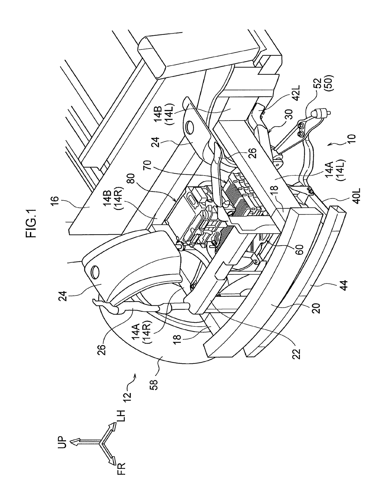
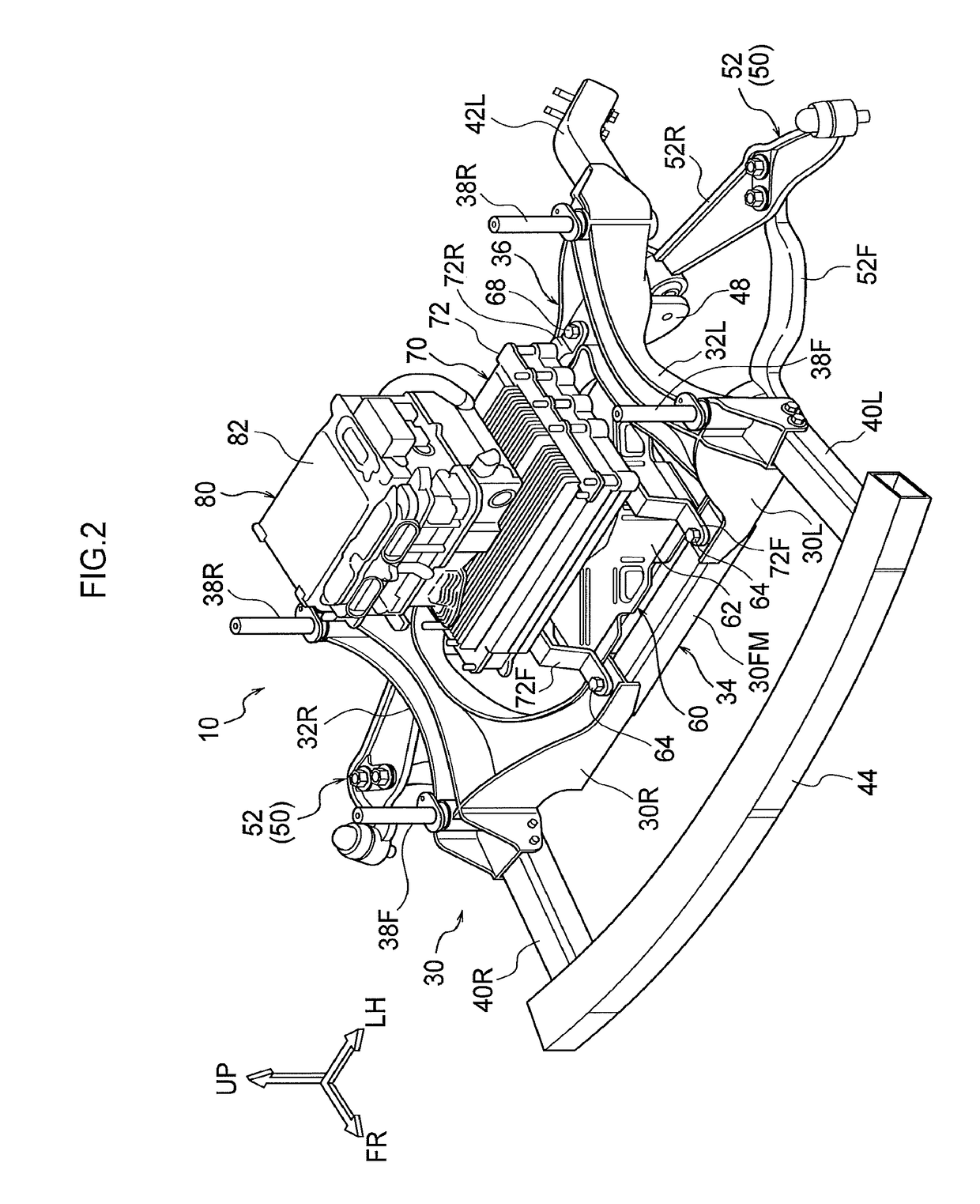
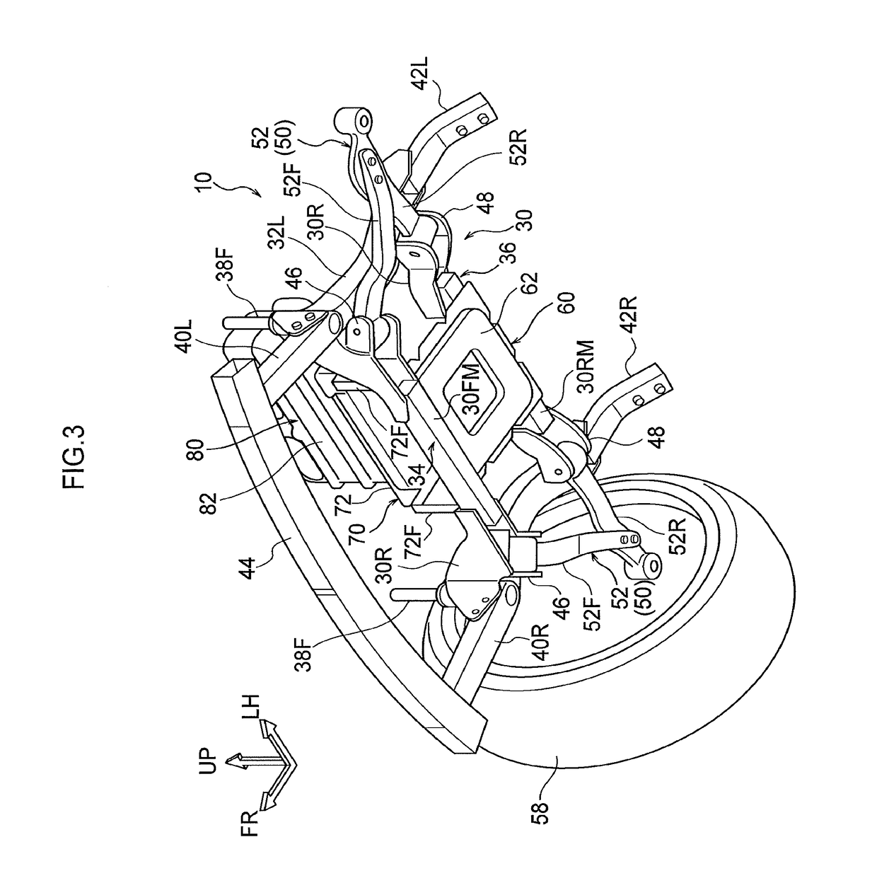
[0026]Explanation follows regarding a vehicle lower section structure 10 according to an exemplary embodiment of the present disclosure, with reference to FIG. 1 to FIG. 8. Note that the arrow FR, the arrow UP, and the arrow LH in the drawings respectively indicate the front direction (direction of travel), upper direction, and left direction of the vehicle, as appropriate. Hereafter, unless specifically stated otherwise, reference simply to the front and rear, left and right, and upward and downward directions refers to the front and rear in a vehicle front-rear direction, left and right in a vehicle left-right direction (vehicle width direction), and upward and downward in a vehicle vertical direction. Moreover, in the drawings, some reference numerals and some members may be omitted in order to aid understanding of the drawings.

[0027]As illustrated in FIG. 1 to FIG. 8, the vehicle lower section structure 10 according to the present exemplary embodiment includes a front suspension...


PUM


Abstract

A vehicle lower section structure includes: a suspension member, formed in a frame shape, including left and right side-rails extending in a vehicle front-rear direction, and front and rear cross members coupling the left and right side-rails together in a vehicle width direction; a contactless charger fastened to both a left side and a right side of a front portion and a rear portion of the suspension member, and being supported by the suspension member; and an electrical component disposed above the contactless charger and is electrically connected to the contactless charger, the electrical component is fastened to both the left side and the right side of the front portion and the rear portion of the suspension member and is supported by the suspension member.

Description

CROSS-REFERENCE TO RELATED APPLICATION[0001]This application claims priority under 35 USC 119 from Japanese Patent Application No. 2017-122365, filed on Jun. 22, 2017, the disclosure of which is incorporated by reference herein.BACKGROUNDTechnical Field[0002]The present disclosure relates to a vehicle lower section structure.Related Art[0003]Japanese Patent Application Laid-Open (JP-A) No. 2014-104976 describes a sub-frame of a front body or a rear body of an automobile. The sub-frame includes left and right side-members, a cross member coupling left and the right side-members together, and a reinforcement structure for increasing twisting rigidity. The reinforcement structure is configured as a plate having shear strength, and has an open space at its center. A charging module is fitted inside the open space. The charging module is one configuration component of the reinforcement structure, and the charging module itself contributes to reinforcement of the sub-frame. The reinforcem...

Claims


Application Information

Patent Timeline
Patent Type & Authority Patents(United States)
IPC IPC(8): B62D21/02H02J7/02
CPCB60L53/12B62D21/02B60L53/22H02J7/025B62D21/00B62D21/11B62D25/08B60L53/126Y02T10/7072Y02T10/70Y02T90/14H02J50/10
Inventor AYUKAWA, TATSUYA
Owner TOYOTA JIDOSHA KK
Learn More