
Method for rating a propulsion unit comprising a main engine and an auxiliary engine

a technology of propulsion unit and main engine, which is applied in the field of engine rating, can solve the problems of less thermodynamic (and therefore energetic) efficiency of engine, less thrust of engine, and greater specific consumption of engine, and achieve the effect of not optimal thermodynamic efficiency in the other flight phases, and less thrust of engin

Pending Publication Date: 2018-12-27
SN DETUDE & DE CONSTR DE MOTEURS DAVIATION S N E C M A
View PDF3 Cites 4 Cited by
  • Summary
  • Abstract
  • Description
  • Claims
  • Application Information

AI Technical Summary

Benefits of technology

The invention proposes a solution for aircraft propulsion that addresses the problem of conflicting operational restrictions, such as the need for ambitious fuel consumption goals and the capacity of the propulsion unit to have an aircraft take off. The invention proposes a rating process for the propulsion unit that determines the optimal distribution of main and auxiliary engine thrust for take off and top of climb operating conditions. The main engine provides the main thrust, while the auxiliary engine provides additional thrust. The rating process takes into account the capacity of the main engine and the auxiliary engine to determine the optimal distribution of thrust. The invention also proposes a propulsion unit with a main engine and an auxiliary engine that work together to provide the necessary thrust for take off and top of climb. The aircraft can also comprise multiple auxiliary engines, with the thrust of each engine participating at 100% of the auxiliary thrust.

Problems solved by technology

Throughout most of the flight, it eventuates that the engine needs lower thrust and therefore exhibits less thermodynamic (and therefore energetic) efficiency.
The result of this during this flight phase is that the specific consumption of the engine is greater than its optimum.
But thermodynamic efficiency in the other flight phases is not optimal, especially at cruise speed.

Method used


Image

  • Method for rating a propulsion unit comprising a main engine and an auxiliary engine
  • Method for rating a propulsion unit comprising a main engine and an auxiliary engine
  • Method for rating a propulsion unit comprising a main engine and an auxiliary engine

Examples


first embodiment

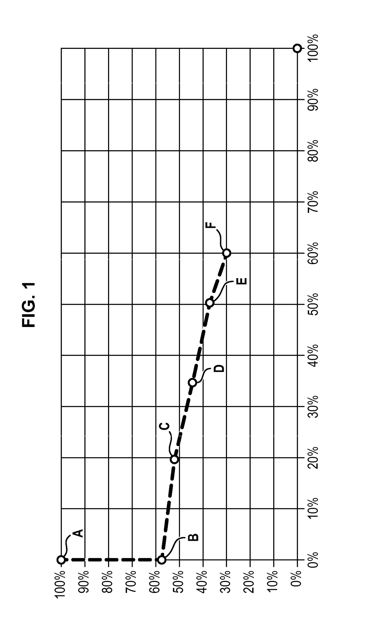
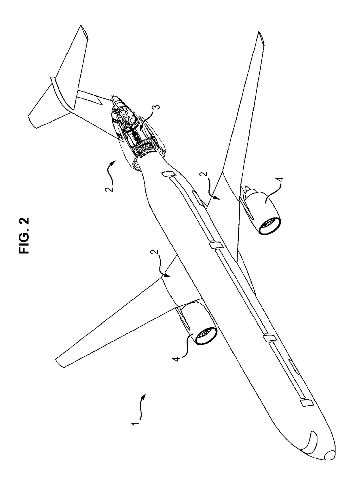
[0057]In a first embodiment, the propulsion unit 2 can be rated such that, during the take off operating condition, the thrust provided by the propulsion unit 2 is obtained at 38% to 42% by the auxiliary engine 4 during the take off operating condition (the complement being provided by the main engine 3) and at 100% by the main engine 3 during the top of climb operating condition.

[0058]This first embodiment is particularly adapted for the aircraft 1 having a mission of short-haul type. In fact, the thermodynamic cycle of the main engine 3 is optimised at top of climb, which improves its specific consumption in comparison with a conventional engine, especially in the operating conditions of top of climb and cruise, without as such needing a large-size auxiliary engine 4, reducing the bulk of the propulsion unit 2 as well as the overload resulting from the addition of an auxiliary engine 4.

second embodiment

[0059]In a second embodiment, the propulsion unit 2 can be rated such that the thrust provided by the propulsion unit 2 is obtained at 47% to 49% by the auxiliary engine 4 during the take off operating condition and at 18% to 21% by the auxiliary engine 4 during the top of climb operating condition, the rest of the thrust being provided by the main engine 3.

[0060]This second embodiment is particularly adapted for the aircraft 1 having a mission of short-haul to medium-haul type. In fact, the thermodynamic cycle of the main engine 3 is improved at top of climb and optimised to the point of maximal corrected engine speed of the fan (N1K), which corresponds to an intermediate operating condition between the top of climb operating condition and the operating cruise condition which is representative of the average use of the plane on this type of mission.

[0061]Typically, the specific consumption of a propulsion unit 2 rated in keeping with this embodiment is further reduced relative to t...

third embodiment

[0062]In a third embodiment, the propulsion unit 2 can be rated such that the thrust provided by the propulsion unit 2 is obtained at 52% to 55% by the auxiliary engine 4 during the take off operating condition and at 33% to 36% by the auxiliary engine 4 during the top of climb operating condition, the rest of the thrust being provided by the main engine 3.

[0063]This third embodiment is particularly adapted for the aircraft 1 having a mission of the medium-haul to long-haul type. In fact, the thermodynamic cycle of the main engine 3 is improved at top of climb and optimised at the point of engine speed of the fan corresponding to 95% of its corrected maximal speed which corresponds to an operating condition of start of cruise of average length, representative of the average use of the plane on this type of mission.

[0064]Typically, the specific consumption of a propulsion unit 2 rated in keeping with this third embodiment is further reduced relative to that of the propulsion unit 2 a...


PUM


Abstract

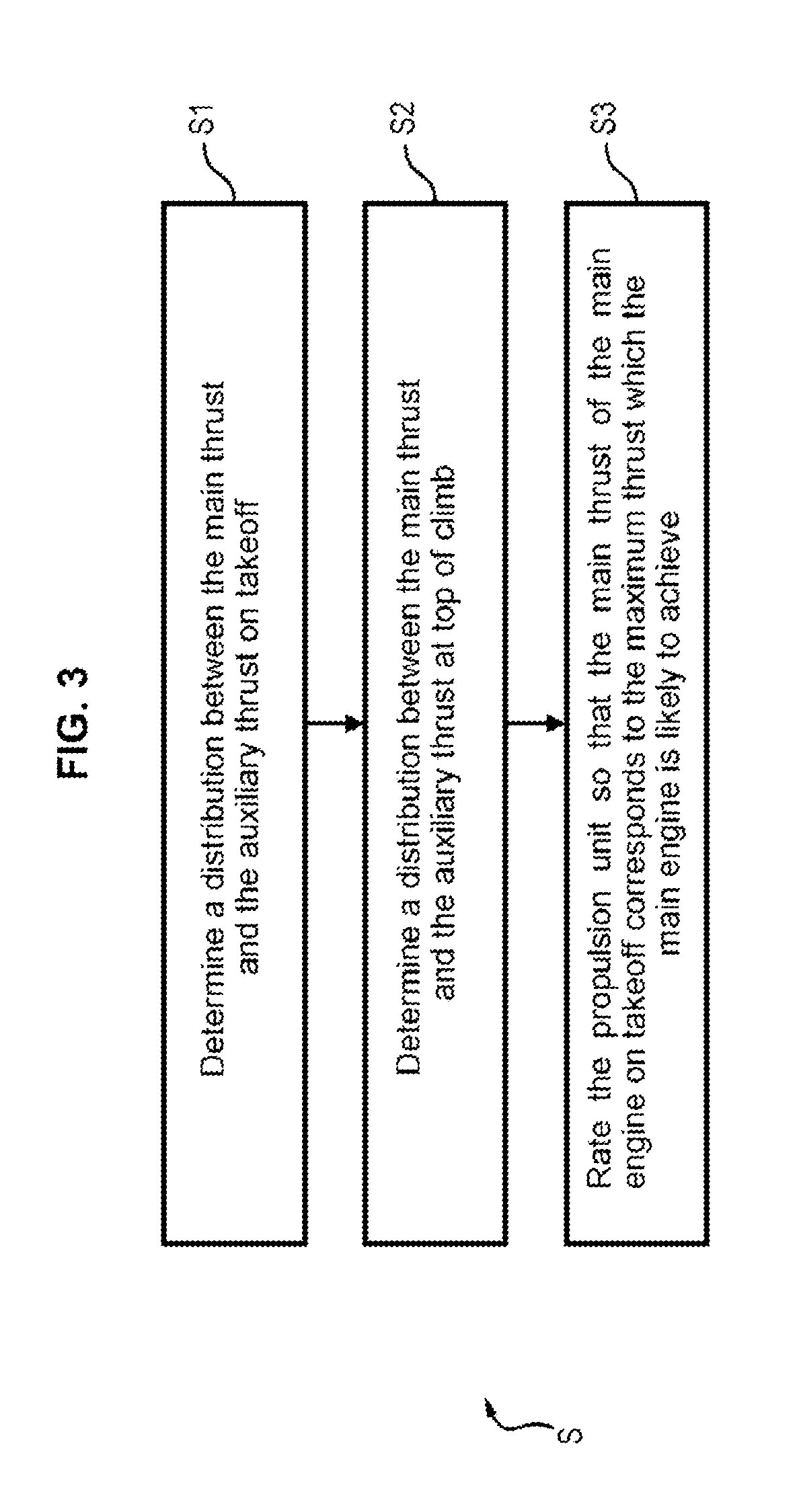
The invention relates to the rating (S) of a propulsion unit (2) comprising a main engine (3) providing main thrust assisted by an auxiliary engine (4) providing auxiliary thrust, according to the following steps: (i) determining (S1) a distribution between the main thrust and the auxiliary thrust so as to obtain the takeoff thrust of the propulsion unit, the auxiliary thrust making a 5% to 65% contribution to the takeoff thrust, (ii) depending on the distribution determined for the takeoff condition, determining (S2) distribution between the main thrust and the auxiliary thrust so its to obtain the top of climb thrust of the propulsion unit, the auxiliary thrust making at most 70% contribution to the top of climb thrust, and (iii) rating (S3) the propulsion unit (2) in such a way that the main thrust of the main engine (3) determined fir the takeoff condition corresponds to the maximum thrust likely to be achieved by the main engine (3).

Description

FIELD OF THE INVENTION[0001]The invention relates to the general field of aircraft, and more particularly of the rating of engines of such aircraft with a view to improving, inter alia, the specific consumption. The invention applies to all the types of aircraft intended to fly missions comprising different operating conditions.TECHNOLOGICAL BACKGROUND[0002]When operating, a given engine is stressed in various ways according to the flight phases of the aircraft. In fact, each phase flight is associated with an engine operating condition, including ground idle, take off, climb, top of climb (or maximum climb) or also cruise. During the above operating conditions, the engine is maintained over a relatively long time (between thirty seconds for take off and several hours for cruise) at predefined speed ranges which depend on the redlines of the engine (specifically the absolute maxima encountered by the operating parameters of the engine such as engine speed of the shafts or the temper...

Claims


Application Information

Patent Timeline
IPC IPC(8): B64D31/00B64D27/24B64D27/10B64D27/16
CPCB64D31/00B64D27/24B64D27/10B64D27/16B64D2027/026B64D27/00B64D27/026
Inventor COAT, PASCAL CHARLES EDOUARDBERSOT, JEAN-FRANCOIS ENDYORCEL, STEPHANETANTOT, NICOLAS JEROME JEAN
Owner SN DETUDE & DE CONSTR DE MOTEURS DAVIATION S N E C M A
Learn More