Cross-flow fan propulsion system

a technology of propulsion system and fan, which is applied in the direction of wind motor with perpendicular air flow, underwater vessels, aircraft navigation control, etc., can solve the problems of limited fan size and ducting, failed to produce adequate propulsion thrust, and failed to meet the test of success, etc., to achieve cost-effective, high maneuverability, and the effect of cross-flow fan propulsion

Inactive Publication Date: 2012-05-10
PROPULSIVE WING
View PDF11 Cites 70 Cited by
  • Summary
  • Abstract
  • Description
  • Claims
  • Application Information

AI Technical Summary

Benefits of technology

[0015]Several aspects of cross-flow fan propulsion are improved. The propulsion system includes a combined propulsor, flow control device, and cargo-carrying platform with large thickness-to-chord ratio cross-section (ranging from 20% up to 50% or more), which provides a compact, cost-effective short takeoff and landing (STOL) or vertical takeoff and landing (VTOL) solution. With its unique thick-wing design, the cross-flow propulsion mechanism within a distributed cross-flow fan wing can carry 3 times the payload weight and 10 times the internal payload volume of conventional systems. For this reason, the aircraft is considered an aerial utility vehicle, or AUV. The platform is also highly maneuverable, generates low noise, and offers a high degree of user safety due to the elimination of external rotating propellers.

Problems solved by technology

Historically, several companies, universities, and individuals have attempted to utilize cross-flow fan propulsion in aircraft; however, most previous attempts met with little or no success due to an inadequate understanding of the flow physics and improper housing design and fan placement.
This design, however, limited the fan size and ducting.
This increased the maximum lift coefficient by delaying stall at high angle of attack, but failed to produce adequate thrust for propulsion.
These configurations were unsuccessful, however, due to improper housing design.

Method used


Image

  • Cross-flow fan propulsion system
  • Cross-flow fan propulsion system
  • Cross-flow fan propulsion system

Examples


embodiment 170

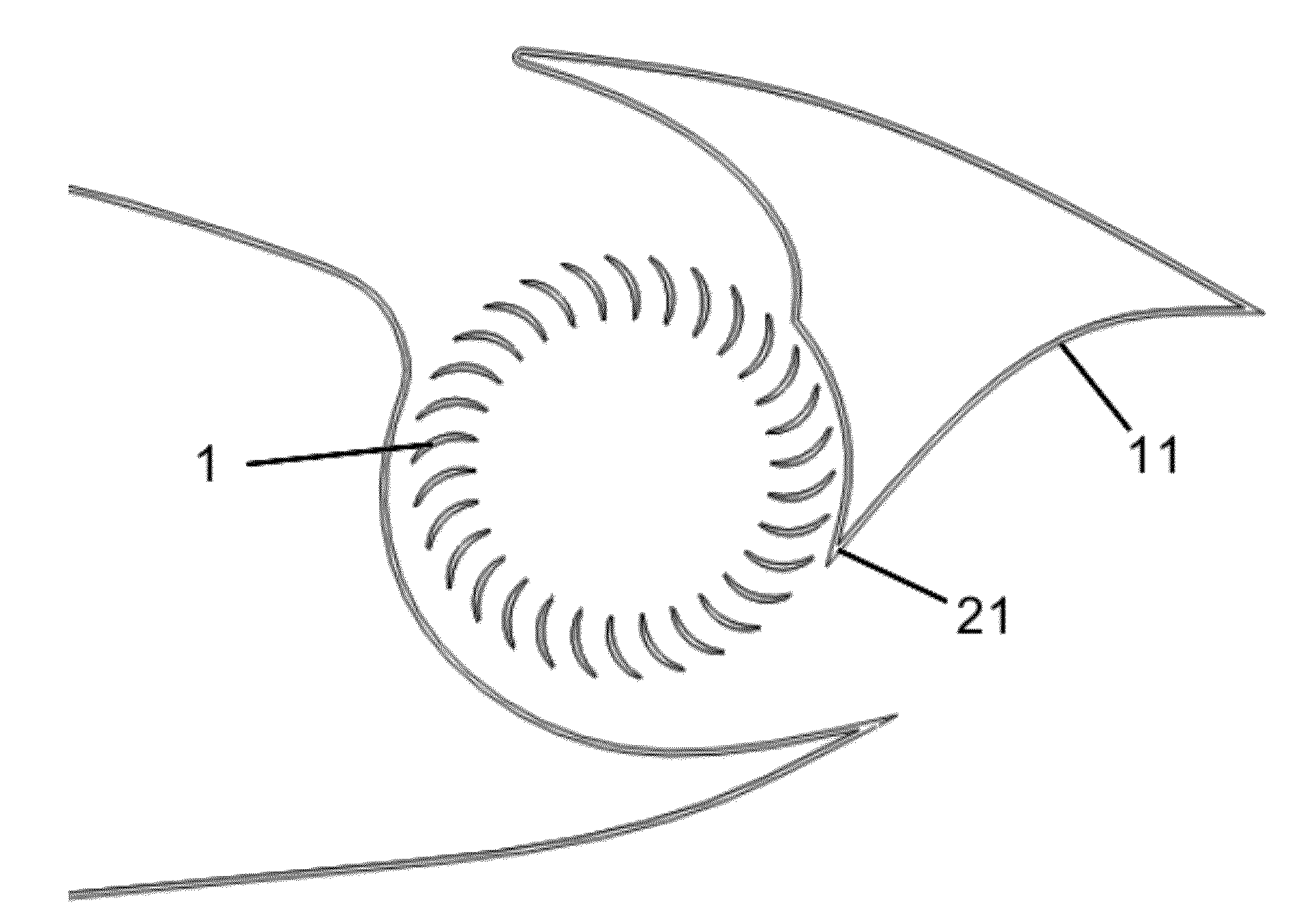
[0081]As an alternative to powering one of the fans for vertical takeoff and landing, with the other shut off, FIGS. 12a and 12b show an embodiment 170 of the cross-flow fan wing system 170 where all fans 111 and 112 can remain on throughout all flight regimes. Here, the fan internal housing 122 is altered with internal baffles and / or moving walls, shown in FIGS. 12a and 12b as dotted lines 123, to properly set up the flow path through fan 112. Here, both fans 111 and 112 remain on for vertical flight and rotate in the same direction. The difference lies in that the housing geometry 122 on one side of the vehicle is dynamically adjusted to that denoted by the dotted lines 123. By doing this, the direction of the flow through the fan is reversed on the side of the plane corresponding to internal geometry 123, creating thrust in opposite directions on each side of the vehicle. The result is a large torque, and subsequent spinning of the vehicle about its center, which produces lift. O...

embodiment 750

[0092]Other embodiments 700 for driving the cross-flow fan are shown in FIGS. 24a, 24b, and 25. In FIGS. 24a and 24b, a turbine engine 243 is used, where power is shafted, through appropriate gearing, to the cross-flow fans 241 and 242. In one preferred embodiment, the turbine engine 243 is a gas turbine engine (also called a combustion engine), although alternative turbine engines could be used. This embodiment preferably uses a small gas turbine engine, and shafts power off of it to drive the fans. This would be done in a manner similar to a turbo-prop engine, where a turbine stage supplies the power to the fan. The resulting system is called a turbo cross-flow fan propulsion system. FIG. 24b shows a schematic of such a system. As an alternative to using a turbine stage to turn a drive-shaft, a turbine 243 can be used to power an electric generator, which in turn provides electric power for electric motors that are used to drive the cross-flow fans. This is an alternative to using...


PUM

PropertyMeasurementUnit
lift coefficientsaaaaaaaaaa
thrust vectoringaaaaaaaaaa
speedaaaaaaaaaa

Abstract

The present invention includes improvements to cross-flow fans and cross-flow fan propelled aircraft including improved control, a dynamically adjustable vortex wall and internal housing, a vortex tube, vertical takeoff and landing rotorcraft configurations, the inclusion of an optimized oscillating blade fan, a wavy vortex wall, power plant refinements, dual leading and trailing edge configurations, stability improvements, tip plates, tapered wings, tapered fans, a fan construction method, and underwater applications.

Description

REFERENCE TO RELATED APPLICATIONS[0001]This application claims one or more inventions which were disclosed in Provisional Application No. 61 / 295,339, filed Jan. 15, 2010, entitled “Improved Cross-Flow Fan Propulsion System”. The benefit under 35 USC §119(e) of the U.S. provisional application is hereby claimed, and the aforementioned application is hereby incorporated herein by reference.BACKGROUND OF THE INVENTION[0002]1. Field of the Invention[0003]This invention relates to cross-flow fans and cross-flow fan propelled vehicles.[0004]2. Description of Related Art[0005]The cross-flow fan (CFF), first disclosed in 1893 in U.S. Pat. No. 507,445 (Mortier), incorporated herein by reference, is used extensively in tower fans, air conditioners, and many other products throughout the heating and ventilation (HVAC) industry. The fan is usually long in relation to the diameter, so the flow approximately remains 2-dimensional (2D) away from the ends. The cross-flow fan uses an impeller with f...

Claims


Application Information

Patent Timeline
Patent Type & Authority Applications(United States)
IPC IPC(8): B64C15/02B23P15/00H05K13/00F01D5/12B64C15/00B63G8/08F01D5/14F01D1/06
CPCB63G8/18Y10T29/49002Y10T29/49336B64C39/005
Inventor KUMMER, JOSEPHALLRED, III, JIMMIE B.
Owner PROPULSIVE WING
Why Eureka
Try Eureka