Head-up display device

a display device and head-up technology, applied in the direction of dashboard fitting arrangement, instruments, transportation and packaging, etc., can solve problems such as affecting driving, and achieve the effect of ensuring design quality and mitigating the restriction of outside dimensions

Active Publication Date: 2018-12-27
PANASONIC INTELLECTUAL PROPERTY MANAGEMENT CO LTD
View PDF0 Cites 4 Cited by
  • Summary
  • Abstract
  • Description
  • Claims
  • Application Information

AI Technical Summary

Benefits of technology

[0005]The present disclosure ensures the quality of design when a combiner of a head-up display device is stored, and mitigates the restriction in the outside dimension of the head-up display device.
[0007]The present disclosure can provide a head-up display device ensuring quality of design when a combiner is stored, and mitigating the restriction of the outside dimension.

Problems solved by technology

However, when the driver does not use the combiner, the standing combiner is in the forward sight of the driver, hindering the driving.

Method used


Image

  • Head-up display device
  • Head-up display device
  • Head-up display device

Examples


Embodiment Construction

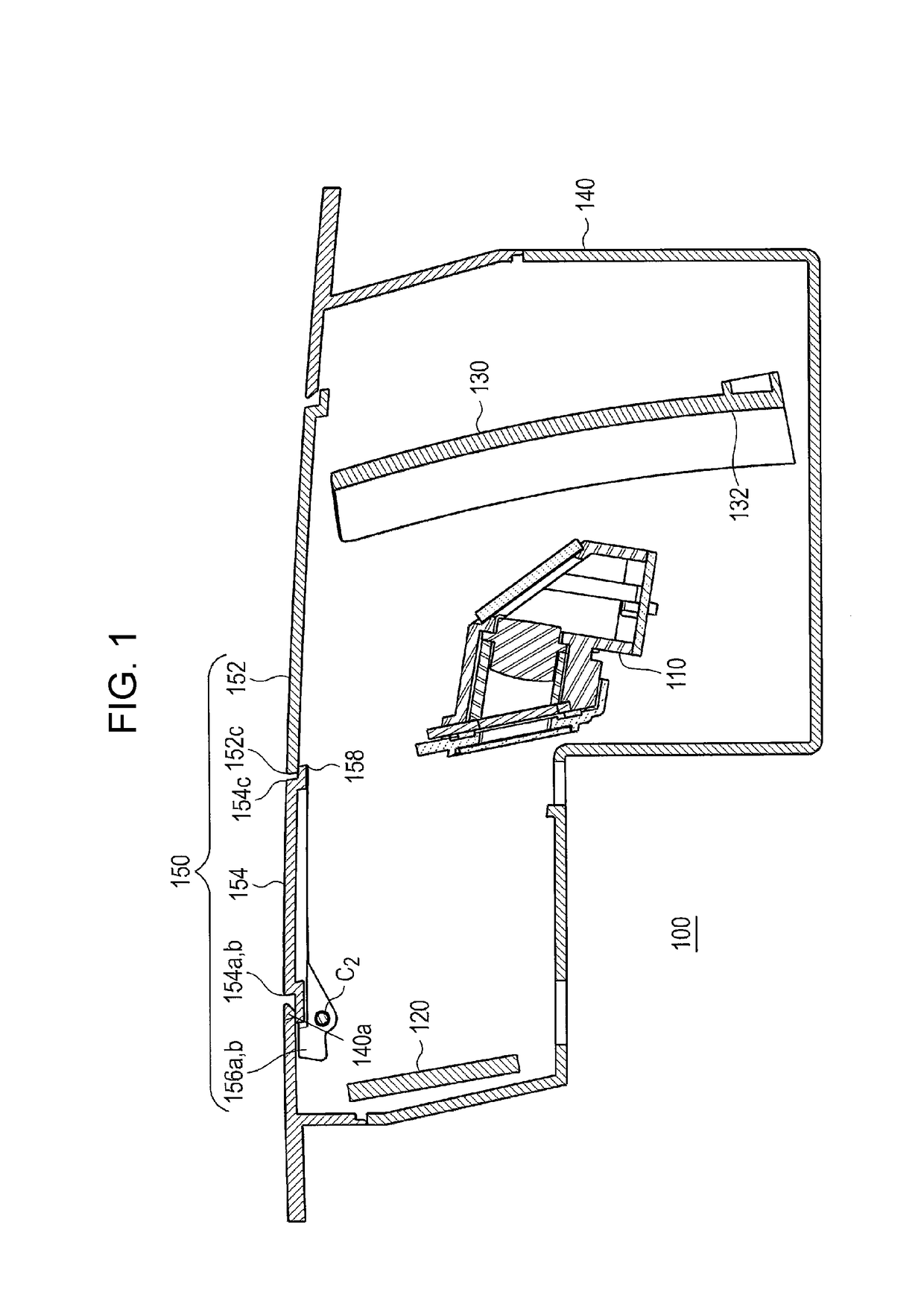
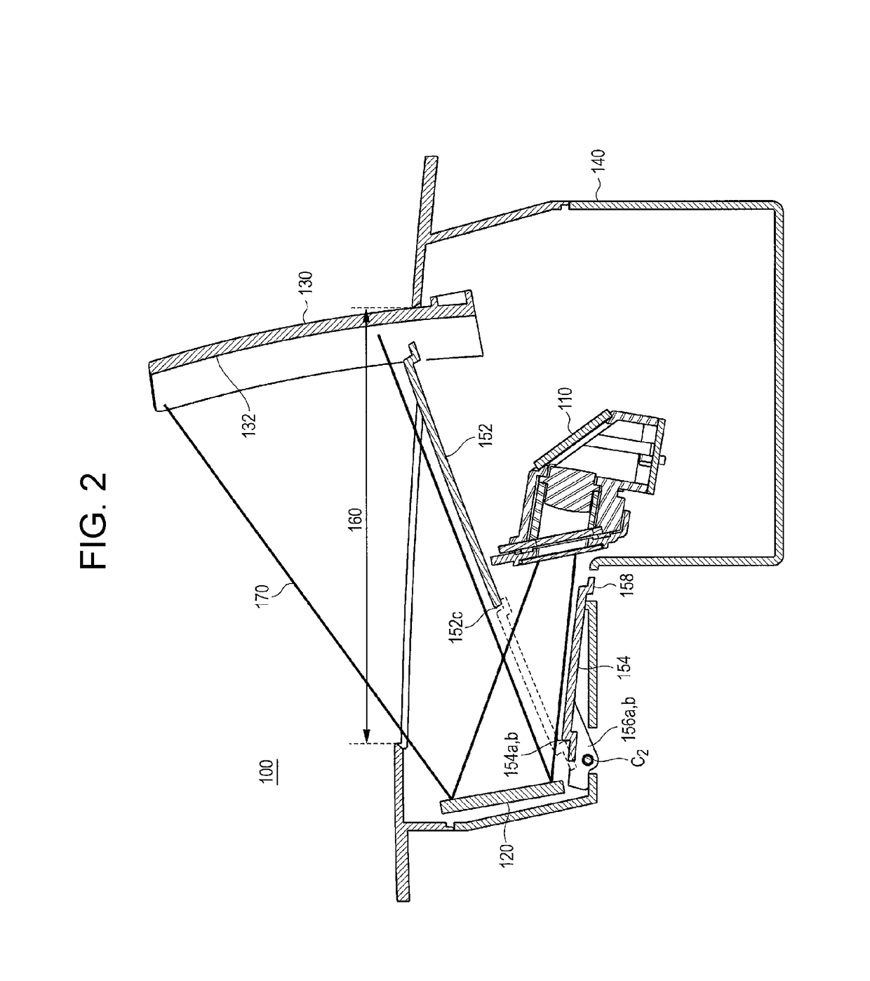
[0015]Prior to the description of the exemplary embodiment of the present disclosure, problems of a conventional head-up display device are described briefly. When a combiner is standing, it is necessary to prevent a cover from obstructing an optical path of light that is emitted from a projector of the head-up display device, reflected by a mirror, and emitted to a combiner. In an example of layouts to solve this problem, a sufficient interval is secured between the mirror and a tip end of the cover. In another example of the layouts arrangement of a projector is adjusted so as to allow the emitting direction of light from the projector to be close to the vertical direction. However, any of these layouts lead to restriction of the outside dimension of the head-up display device, making it difficult to reduce the size of the head-up display device.

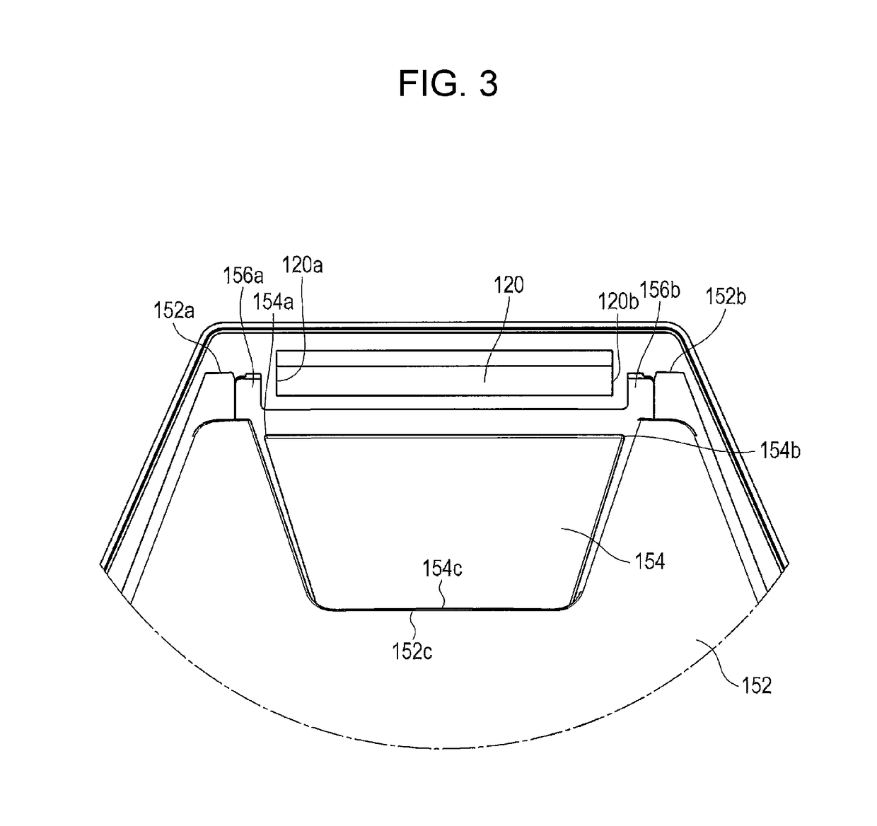
[0016]Hereinafter, the exemplary embodiments of the present disclosure are described in detail with reference to drawings.

[0017]FIG. 1 is...


PUM


Abstract

First and second cover members of a cover of a head-up display device cover an opening region of a housing. The first cover member is rotationally movable with respect to the housing around a first rotation fulcrum fixed to the housing. The second cover member is rotationally movable with respect to the first cover member around second rotation fulcrums respectively fixed to first and second end parts of the first cover member. When the first cover member turns with respect to the housing and the second cover member turns with respect to the first cover member, the first end part is located at an outer side than a first side of a mirror, and the second end part is located at an outer side than a second side of the mirror. The second cover member is not present in an optical path of light projected from a projector to the mirror.

Description

CROSS-REFERENCE TO RELATED APPLICATIONS[0001]This application is a continuation of the PCT International Application No. PCT / JP2016 / 005234 filed on Dec. 27, 2016, which claims the benefit of foreign priority of Japanese patent application No. 2016-034352 filed on Feb. 25, 2016, the contents all of which are incorporated herein by reference.BACKGROUND1. Technical Field[0002]The present disclosure relates to a head-up display device.2. Description of the Related Art[0003]Conventionally, a head-up display (HUD) to be installed in vehicles such as an automobile is known. Known examples of the head-up displays include one that assists a driver by displaying information on a combiner. The combiner is disposed to stand in front of a driver. However, when the driver does not use the combiner, the standing combiner is in the forward sight of the driver, hindering the driving.[0004]In order to solve such a problem, a head-up display device equipped with a storage device is disclosed (see Japa...

Claims


Application Information

Patent Timeline
Patent Type & Authority Applications(United States)
IPC IPC(8): G02B27/01G02B27/09G03B21/20G03B21/14
CPCG02B27/0101G02B27/0977G03B21/2066G03B21/145G02B2027/014B60K2350/2052B60K35/00B60K37/00G02B27/01B60K2370/334G02B27/0149B60K2370/66B60K2370/67B60K2370/682B60K2370/1529G02B2027/0156B60K37/04G02B2027/0154
Inventor NAKAYAMA, KENJI
Owner PANASONIC INTELLECTUAL PROPERTY MANAGEMENT CO LTD
Why Eureka
Try Eureka