Projection apparatus that improves dynamic range of luminance of printed material, control method therefor, and storage medium

Inactive Publication Date: 2018-12-27
CANON KK
View PDF0 Cites 1 Cited by
  • Summary
  • Abstract
  • Description
  • Claims
  • Application Information

AI Technical Summary

Benefits of technology

[0010]The present invention provides a projection apparatus and a control method therefor which are capable of displaying an OSD from

Problems solved by technology

This means that in this case, a dynamic range which an HDR image originally has is not expressed to a satisfactory degree.
However, according to the techniques disclosed in Japanese Laid-Open Patent Publication (Kokai) No. 2008-83180 and International Publication No. 05/057941 above, it is diffic

Method used


Image

  • Projection apparatus that improves dynamic range of luminance of printed material, control method therefor, and storage medium
  • Projection apparatus that improves dynamic range of luminance of printed material, control method therefor, and storage medium
  • Projection apparatus that improves dynamic range of luminance of printed material, control method therefor, and storage medium

Examples


embodiment 1

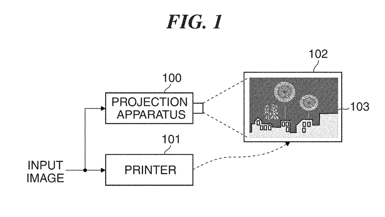
[0022]FIG. 1 is a diagram useful in explaining an image display system that uses a projection apparatus 100 according to embodiment 1.

[0023]First, the same input image is input to the projection apparatus 100 and a printer 101. The projection apparatus 100 performs predetermined image processing on the input image to generate a projected image 103 and then projects the projected image 103 onto a projection surface. Operations performed in the projection apparatus 100 will be described later in detail.

[0024]The printer 101 prints the input image and outputs a printed material 102. The printed material 102 is placed on the projection surface of the projection apparatus 100. It should be noted that the projected image 103 is projected from the projection apparatus 100 in a manner being superimposed on the printed matter 102 placed on the projection surface. By thus projecting the projected image 103 relating to the printed material 102, a dynamic range of luminance of the printed mater...

embodiment 2

[0077]FIG. 6 is a diagram useful in explaining an image display system that uses a plurality of the projection apparatuses 100A and 100B according to embodiment 2. An internal arrangement of the projection apparatuses 100A and 100B is the same as that of the projection apparatus 100 in the embodiment 1 described above.

[0078]The same input image is input to the projection apparatuses 100A and 100B. The projection apparatuses 100A and 100B perform predetermined image processing to generate projected images 103A and 103B, respectively, and then project the projected images 103A and 103B onto the projection surface in a manner being superimposed on each other.

[0079]Here, a description will be given of how the components of the projection apparatus 100A according to the present embodiment operate in a case where the projection apparatus 100A displays an OSD. These operations are substantially the same as those of the projection apparatus 100 described above in the embodiment 1 with refer...

embodiment 3

[0094]In the embodiments 1 and 2 described above, the pattern color correction is performed for an area where an OSD is superimposed in an image signal on which the OSD is superimposed by the OSD superimposing unit 142.

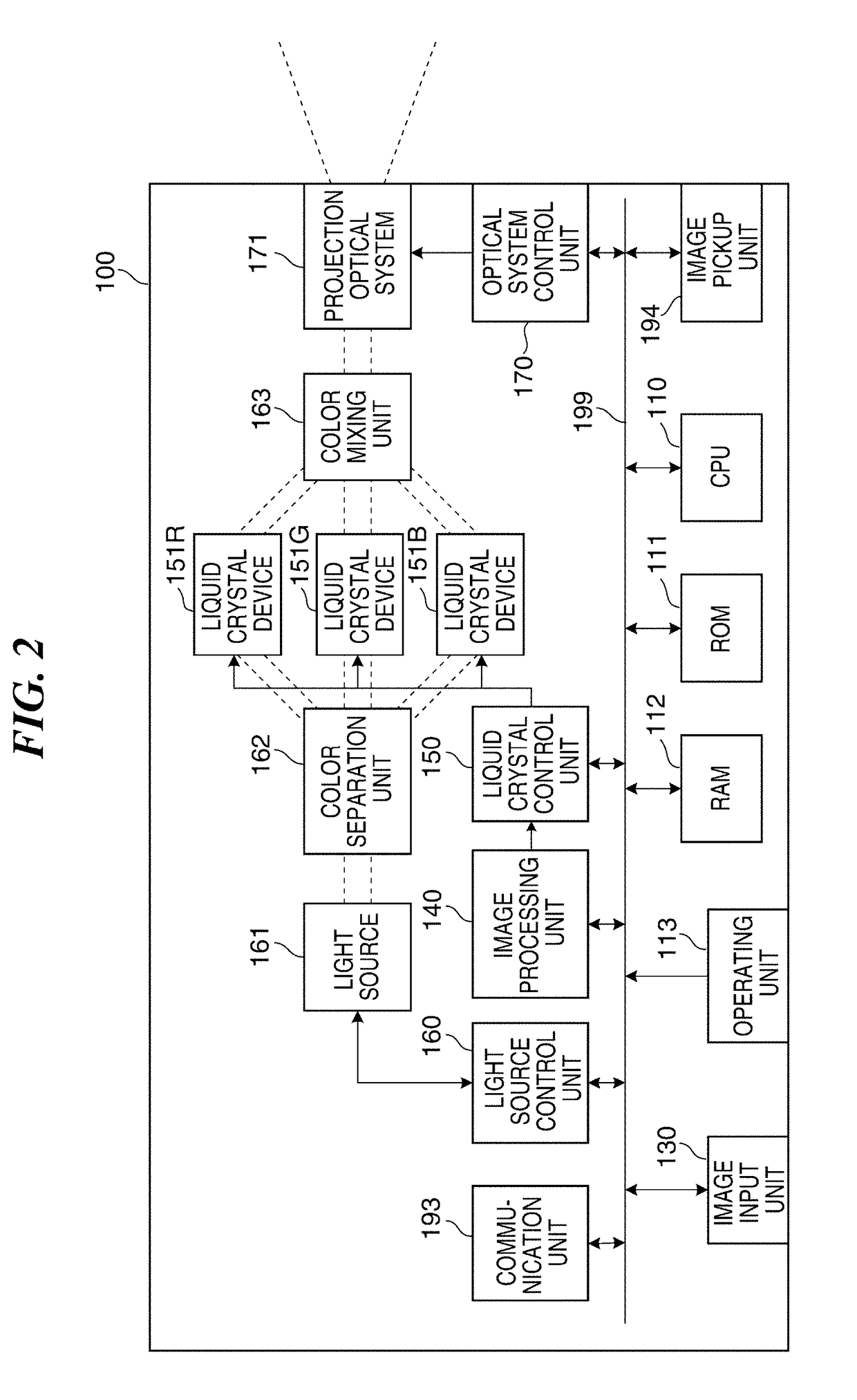
[0095]On the other hand, a projection apparatus 100C according to embodiment 3 performs pattern color correction on an OSD before the OSD is superimposed by the OSD superimposing unit 142. It should be noted that an image processing unit 140A of the projection apparatus 100C according to the present embodiment has substantially the same hardware arrangement as the one shown in FIG. 2, and therefore, the same components as those in FIG. 2 are designated by the same reference symbols, detailed description of which, therefore, is omitted.

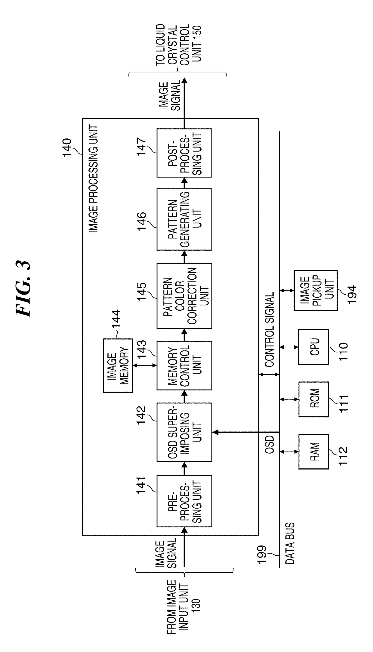
[0096]FIG. 7 is a diagram showing an internal arrangement of the image processing unit 140A in FIG. 2 according to the present embodiment.

[0097]An OSD recorded in the ROM 110 is input first to the pattern color correction unit 145. The p...


PUM


Abstract

A projection apparatus which is capable of displaying an OSD from the projection apparatus in an easily viewable manner while maintaining an image quality improving effect. An image is projected on an observed object of a projection surface based on a projected image. A predetermined image is superimposed on the projected image. Pattern color correction is performed for at least an area of the projected image. In a case where an image based on the projected image superimposed with the predetermined image is projected, the pattern color correction is performed for an area of the projected image where the predetermined image is superimposed, whereas the pattern color correction is not performed for another area of the projected image.

Description

BACKGROUND OF THE INVENTIONField of the Invention[0001]The present invention relates to a projection apparatus, a control method therefor, and a storage medium, and in particular to a projection apparatus and a control method therefor which improve a dynamic range of luminance of printed matter by superimposing a projected image onto the printed matter from the projection apparatus, as well as a storage medium.Description of the Related Art[0002]Lately, there are increasing opportunities to handle an image of a subject shot by a digital camera or the like as a high dynamic range image having a high dynamic range (hereafter referred to as an “HDR image”).[0003]It is expected that usage of HDR images will increase because expressive power for color, gradation, texture, and so forth can be increased by faithfully reproducing a contrast of a subject as actually seen by a person.[0004]On the other hand, although direct-view-type devices such as liquid crystal displays and organic EL disp...

Claims


Application Information

Patent Timeline
IPC IPC(8): H04N1/60G06K15/02B41J29/393
CPCH04N1/644H04N1/6033B41J29/393G06K15/027
Inventor OKA, NOBUHIRO
Owner CANON KK
Why Eureka
Try Eureka