A collimator and collimator arrangement

a collimator and collimator technology, applied in the field of collimator and collimator arrangement, can solve the problems of inability to meet the depth requirements of a cob led, the depth required by a cob led is not available, and the cost of providing a cob led is more than the number, so as to achieve the effect of filling even more effectively

Active Publication Date: 2019-01-03
SIGNIFY HLDG BV
View PDF0 Cites 2 Cited by
  • Summary
  • Abstract
  • Description
  • Claims
  • Application Information

AI Technical Summary

Benefits of technology

[0045]In all designs, each individual collimator may comprise a third or further sections with different diameters. In this way, the gaps in a desired outer shape are filled even more effectively.

Problems solved by technology

However, providing a COB LED is more expensive than providing a number of separated LEDs, and the optics for a single combined light source takes up a greater depth than an array of small collimators.
In many LED devices, the depth required by a COB LED is unavailable since other parts of the device, such as the heat sink and driver, take up a significant proportion of the available space.
Usually, light that is not captured by the removed section of the total internal reflection surface will be at least partially lost which leads to a sharp efficiency drop.

Method used


Image

  • A collimator and collimator arrangement
  • A collimator and collimator arrangement
  • A collimator and collimator arrangement

Examples


Embodiment Construction

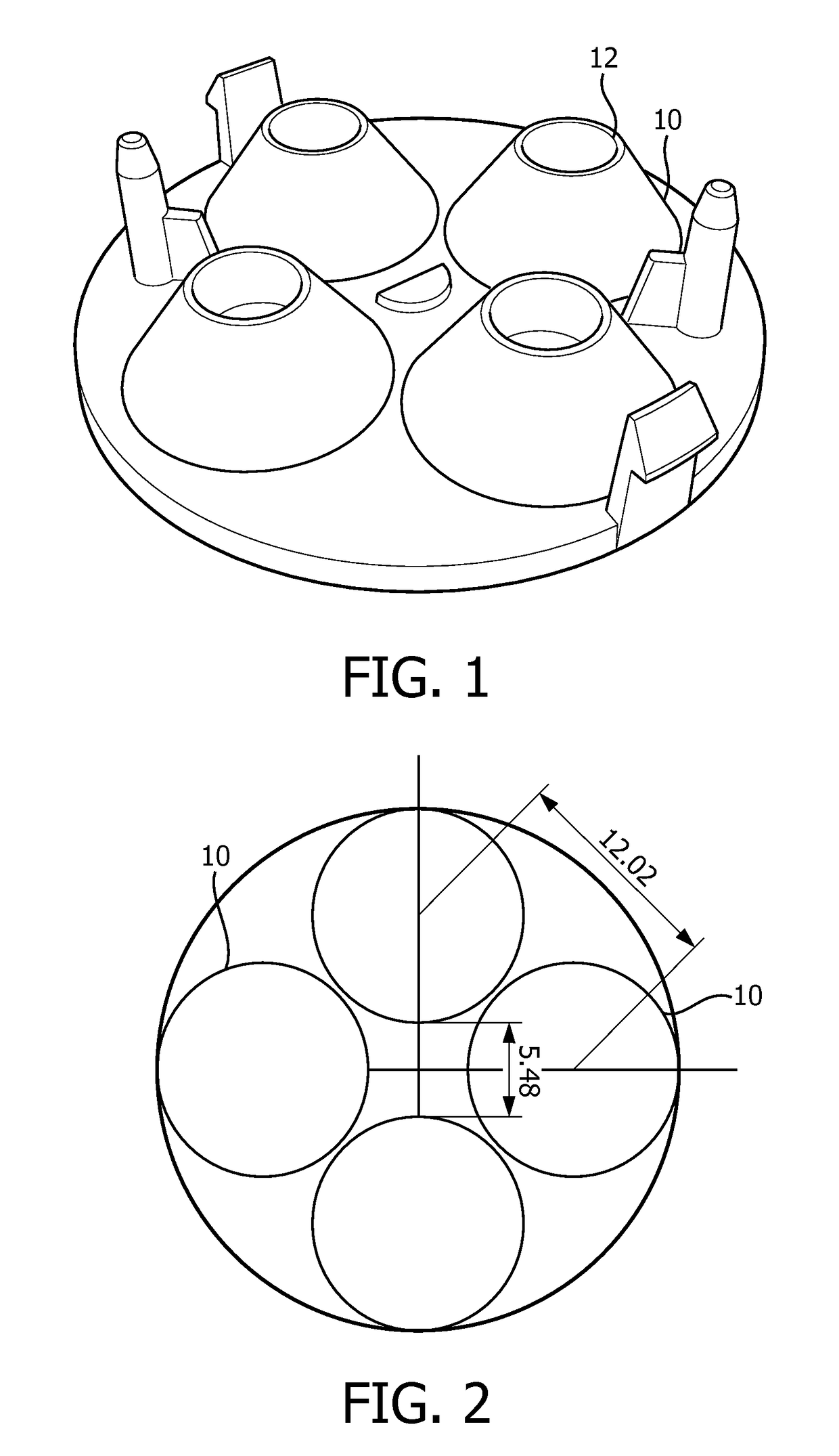
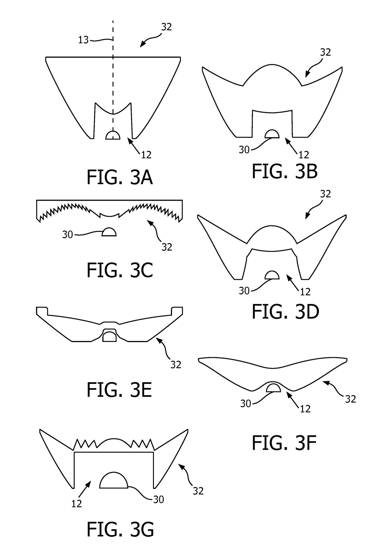
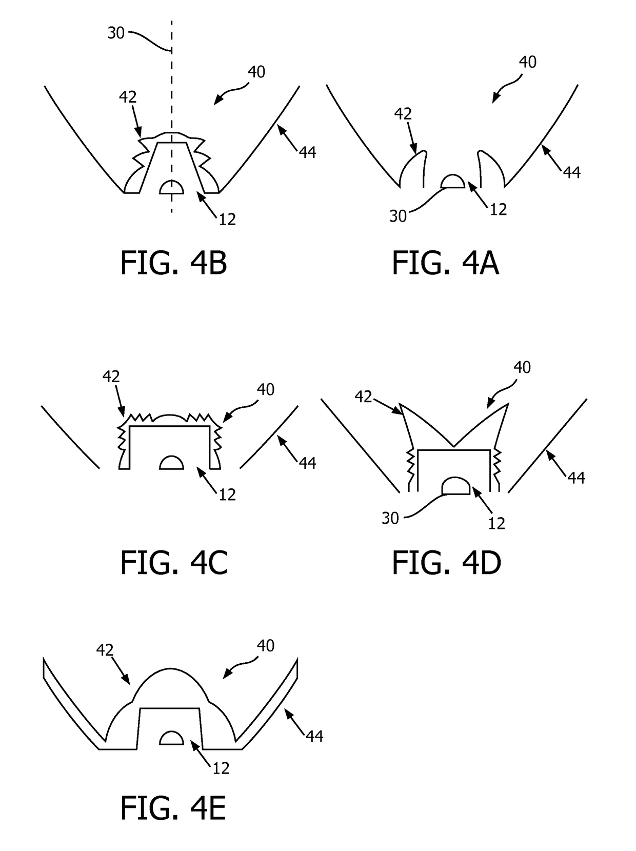
[0065]The invention provides various designs for enabling a non-circular area of collimated light output or to enable tessellation of collimators. In a first aspect, a collimator arrangement comprises a plurality of collimators, each having a circular general outer shape with one or more indentation into the circular general outer shape, wherein each indentation comprises a pair of edges which meet at an internal angle and each indentation defines a pair of external angles where the cut-out meets the general outer shape. The collimators are tessellated with each internal angle adjacent one of the external angles of an adjacent collimator. In another aspect, a collimating optical structure comprises a first section comprising one or more sectors of a first collimator lens design with a first diameter and a second section comprising one or more sectors of a second collimator lens design with a larger, second diameter. The sectors together form an annular shape around the optical axis ...


PUM


Abstract

The invention provides various designs for enabling a non-circular area of collimated light output or to enable tessellation of collimators. In a first aspect, a collimator arrangement comprises a plurality of collimators, each having a circular general outer shape with one or more indentation into the circular general outer shape, wherein each indentation comprises a pair of edges which meet at an internal angle and each indentation defines a pair of external angles where the cut-out meets the general outer shape. The collimators are tessellated with each internal angle adjacent one of the external angles of an adjacent collimator. In another aspect, a collimating optical structure comprises a first section comprising one or more portions of a first collimator lens design with a first diameter and a second section comprising one or more portions of a second collimator lens design with a larger, second diameter. The portions comprise sectors which together form an annular shape around the optical axis with non-constant radius from the optical axis.

Description

FIELD OF THE INVENTION[0001]This invention relates to lighting arrangements, and in particular lighting arrangements which make use of one or more collimators.BACKGROUND OF THE INVENTION[0002]Collimators, for example collimators used for light emitting diode (LED) applications, are usually round. When several LEDS are required, a plurality of round collimators are typically provided and arranged in an array, known as a “shower head” array. The shape of the collimators means that the array includes unlit areas as a consequence of the lack of tessellation of the round collimators.[0003]Instead of several LEDs, a single light source (e.g. a chip on board (COB) LED) can be used with a single collimator. However, providing a COB LED is more expensive than providing a number of separated LEDs, and the optics for a single combined light source takes up a greater depth than an array of small collimators. In many LED devices, the depth required by a COB LED is unavailable since other parts o...

Claims


Application Information

Patent Timeline
Patent Type & Authority Applications(United States)
IPC IPC(8): F21V13/04F21V5/04F21V7/00G02B19/00
CPCF21V13/04F21V5/04F21V7/0091G02B19/0028G02B19/0061G02B19/0066F21V5/007G02B17/002G02B27/0961G02B27/30
Inventor DROSS, OLIVERVISSENBERG, MICHEL CORNELIS JOSEPHUS MARIEANSEMS, JOHANNES PETRUS MARIA
Owner SIGNIFY HLDG BV
Why Eureka
Try Eureka