
Lens assembly with integrated feedback loop and time-of-flight sensor

Active Publication Date: 2019-01-10
COGNEX CORP
View PDF0 Cites 12 Cited by
  • Summary
  • Abstract
  • Description
  • Claims
  • Application Information

AI Technical Summary

Benefits of technology

The patent describes a technology that can detect and analyze objects using a camera-based reader. It can measure the shape of objects and detect damaged objects, such as boxes. It can also identify specific parts of the image where the object is located and reduce the time needed to decode the ID code. Additionally, the technology can detect gaps between objects and help link ID codes to the appropriate object.

Problems solved by technology

In addition, the cost of the lens and / or the available space for mounting the vision system can also drive the choice of lens.
However, due to thermal drift and other factors, there may be variation in calibration and focus setting during runtime use, and over time in general.
However, these can require processing time (within the camera's internal processor) that slows the lens' overall response time in coming to a new focus.
This poses a burden to the vision system's processor, which can be based on a DSP or similar architecture.
That is vision system tasks would suffer if the DSP were continually preoccupied with lens-control tasks.
This presents challenges for the vision system.
Various techniques allow for 3D imaging, but they may not be cost-effective or suitable for a logistics (or similar) environment where a main goal is detecting presence of a surface containing an ID and acquiring a decodable image of the ID as rapidly and efficiently as possible.

Method used


Image

  • Lens assembly with integrated feedback loop and time-of-flight sensor
  • Lens assembly with integrated feedback loop and time-of-flight sensor
  • Lens assembly with integrated feedback loop and time-of-flight sensor

Examples


Embodiment Construction

[0033]I. Vision System Camera Lens

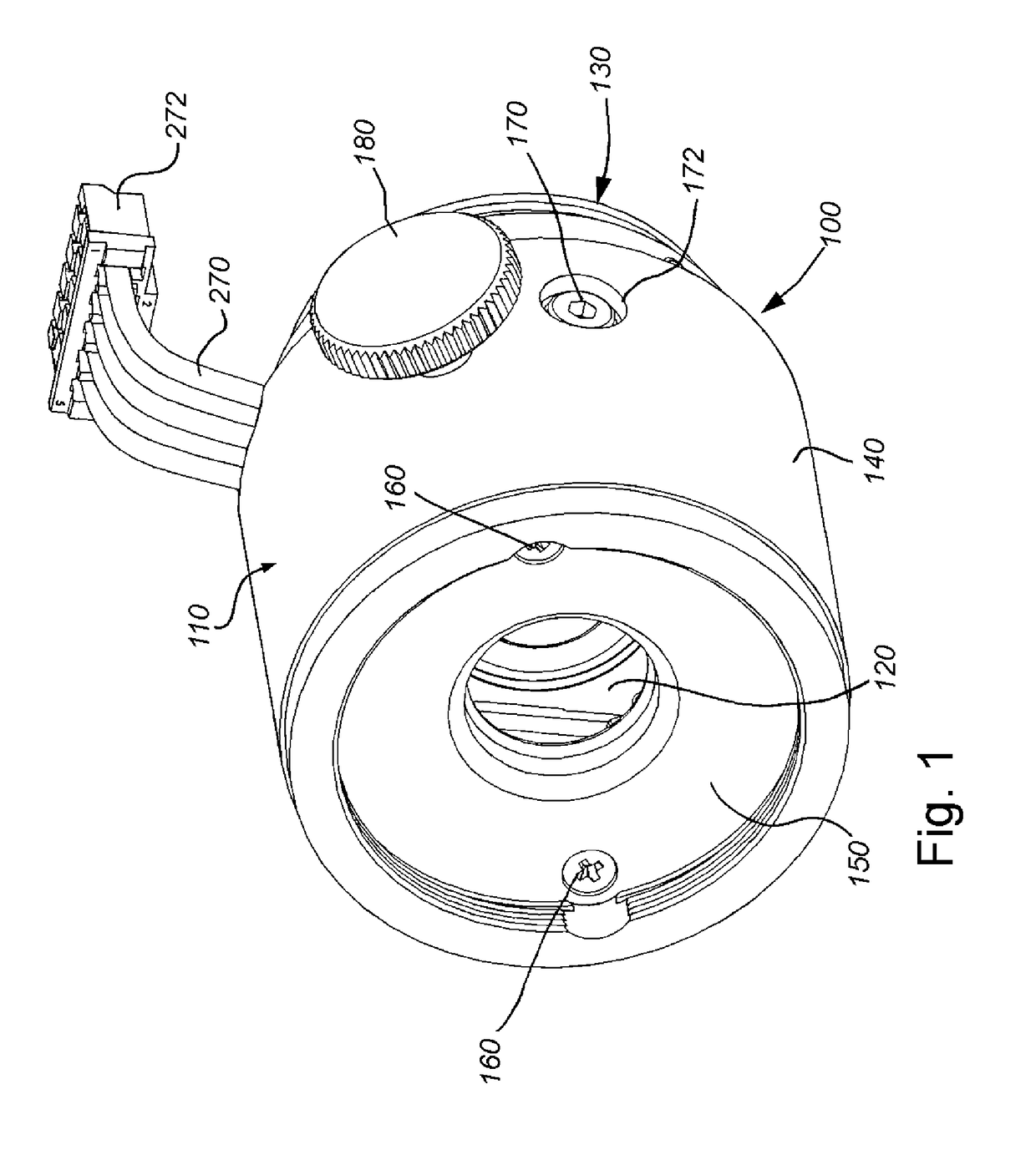
[0034]FIG. 1 details the external structure of an exchangeable, auto-focus lens assembly (also simply termed “lens assembly”) 100 according to an illustrative embodiment. The lens assembly includes an outer cap 110 defining a generally cylindrical shape. This outer cap 110 provides a protective and supporting shell for a variable focus lens element (comprising an Optotune membrane-based liquid lens model EL-6-18 or EL-10-30 in this exemplary embodiment) 120. By way of useful background information the present data sheet with specifications for various models of this lens is available on the World Wide Web at www.optotune.com / images / products / Optotune%20EL-6-18.pdf. It is expressly contemplated that the teachings of the embodiments herein can be applied to a variety of electronically focused lens types including other forms of liquid lens technology and electro-mechanically adjusted solid lenses. For the purposes of this description, the variable focu...


PUM


Abstract

This invention provides an integrated time-of-flight sensor that delivers distance information to a processor associated with the camera assembly and vision system. The distance is processed with the above-described feedback control, to auto-focus the camera assembly's variable lens during runtime operation based on the particular size / shape object(s) within the field of view. The shortest measured distance is used to set the focus distance of the lens. To correct for calibration or drift errors, a further image-based focus optimization can occur around the measured distance and / or based on the measured temperature. The distance information generated by the time-of-flight sensor can be employed to perform other functions. Other functions include self-triggering of image acquisition, object size dimensioning, detection and analysis of object defects and / or gap detection between objects in the field of view and software-controlled range detection to prevent unintentional reading of (e.g.) IDs on objects outside a defined range (presentation mode).

Description

RELATED APPLICATION[0001]This application is a continuation-in-part of co-pending U.S. patent application Ser. No. 13 / 800,055, entitled LENS ASSEMBLY WITH INTEGRATED FEEDBACK LOOP FOR FOCUS ADJUSTMENT, filed Mar. 13, 2013, the teachings of which are expressly incorporated herein by reference.FIELD OF THE INVENTION[0002]This application relates to cameras used in machine vision and more particularly to automatic focusing lens assemblies and range finders in cameras.BACKGROUND OF THE INVENTION[0003]Vision systems that perform measurement, inspection, alignment of objects and / or decoding of symbology (e.g. bar codes, or more simply “IDs”) are used in a wide range of applications and industries. These systems are based around the use of an image sensor, which acquires images (typically grayscale or color, and in one, two or three dimensions) of the subject or object, and processes these acquired images using an on-board or interconnected vision system processor. The processor generally ...

Claims


Application Information

Patent Timeline
IPC IPC(8): G01S17/10H04N5/225H04N5/232G02B7/04G01S7/486G01S17/86
CPCG01S17/10H04N5/2254G01S7/486H04N5/2253G02B7/04H04N5/23212G01S17/36G02B7/08G02B7/40G01S17/86H04N23/55H04N23/671H04N23/54H04N23/67
Inventor WEBER, ANDREASNUNNINK, LAURENSDELASAUCE, RENEEQUITZ, WILLIAM
Owner COGNEX CORP
Learn More