
Lighting device projecting two vertically offset matrices of light pixels

Active Publication Date: 2019-01-17
VALEO VISION SA
View PDF5 Cites 3 Cited by
  • Summary
  • Abstract
  • Description
  • Claims
  • Application Information

AI Technical Summary

Benefits of technology

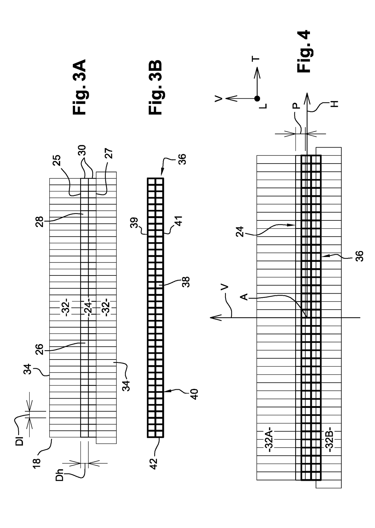
[0023]This makes it possible to obtain a vertical resolution that is uniform over all the height of the zone lit by the two matrices. The vertical resolution is thus greater than the resolution of a single matrix. The vertical resolution is for example multiplied by a factor strictly greater than 1 that can range up to 2 compared to a single matrix comprising pixels of a height similar to those of just one of the two matrices.
[0024]According to another aspect of the invention, the matrices comprise more columns than rows. This makes it possible in particular to light the road over all of its width and over a sufficient range to produce the “ADB

Problems solved by technology

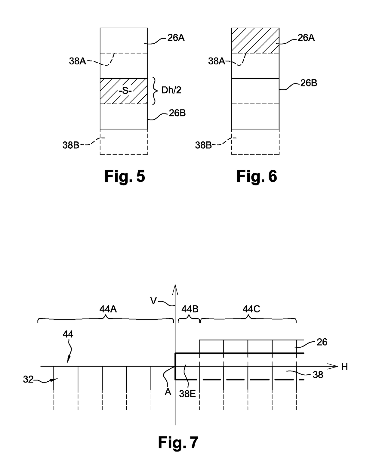
However when a first light pixel is switched off, a portion of the spa

Method used


Image

  • Lighting device projecting two vertically offset matrices of light pixels
  • Lighting device projecting two vertically offset matrices of light pixels
  • Lighting device projecting two vertically offset matrices of light pixels

Examples


Example

DETAILED DESCRIPTION OF THE FIGURES

[0039]Hereinafter in the description, elements that have an identical structure or similar functions will be designated by the same reference.

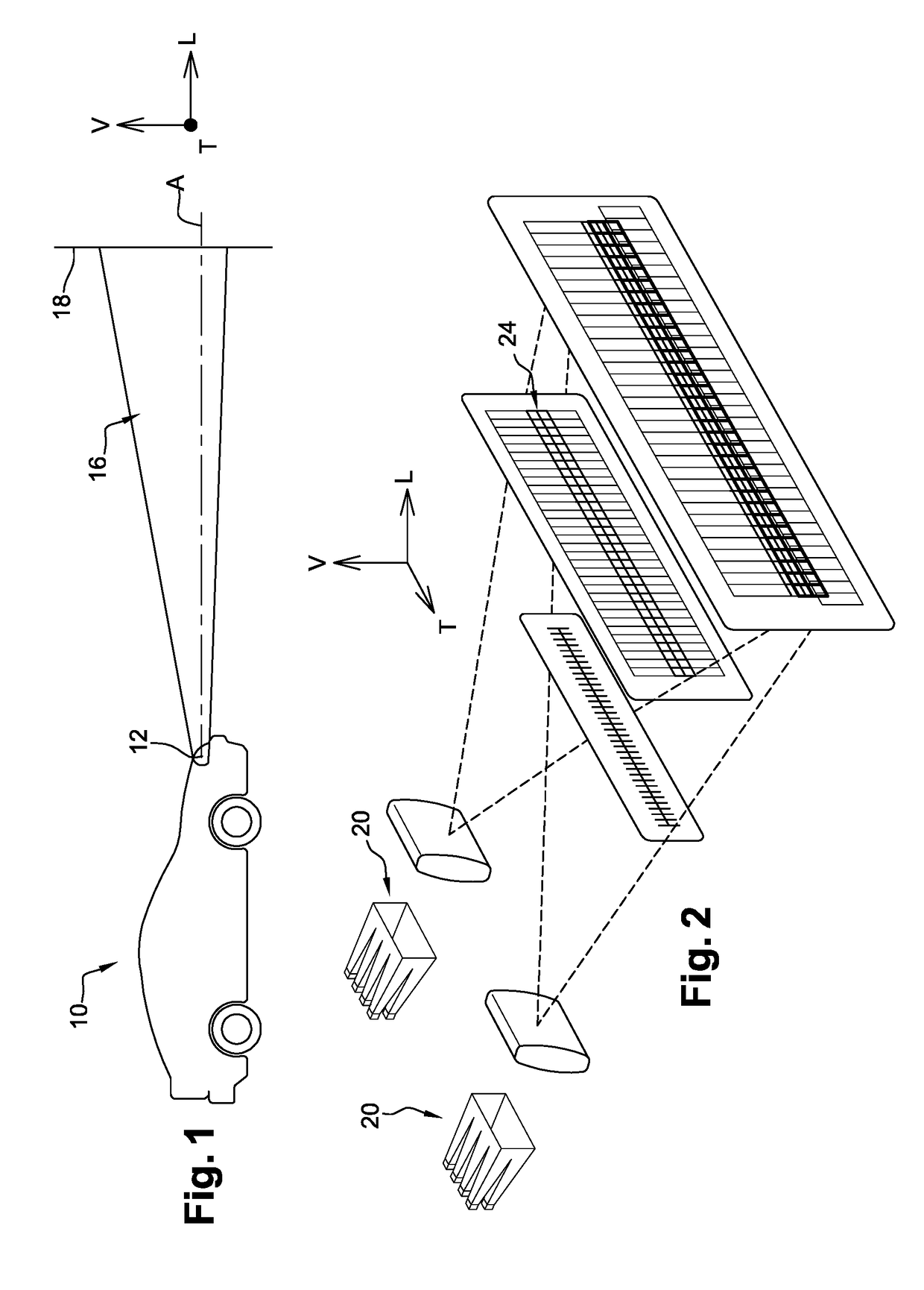
[0040]Hereinafter in the description, orientations that are longitudinal, oriented from back to front in the direction of normal movement of the vehicle, vertical, oriented from bottom to top, and transverse, oriented from left to right, indicated by the “L,V,T” trihedron of the figures, will be adopted in a nonlimiting manner.

[0041]FIG. 1 shows a motor vehicle 10 equipped with a lighting device 12 which produces a light beam with light pixels 16 which produces a determined lighting function. Here, it is a high beam function. The light beam with light pixels 16 is emitted along an axis “A” of emission that is substantially longitudinal to the front of the vehicle 10.

[0042]For the requirements of the description, a vertical transverse screen 18 has been arranged at a determined longitudinal distance in front o...


PUM


Abstract

A lighting device for a motor vehicle including a first lighting module projecting at least one first matrix of first independently activatable juxtaposed pixels, the first pixels being arranged in several vertical columns and in at least one transverse row of determined height (Dh), characterized in that it includes a second lighting module projecting a second matrix of second independently activatable juxtaposed pixels, the second pixels being arranged in at least one transverse row, the second matrix being superposed with the first matrix with a vertical offset by a vertical offset distance (P) less than the determined height (Dh) relative to the first pixels of the first matrix.

Description

TECHNICAL FIELD OF THE INVENTION[0001]The invention relates to a lighting device for a motor vehicle comprising at least one first optical module projecting a matrix of juxtaposed light pixels.TECHNICAL BACKGROUND OF THE INVENTION[0002]Lighting devices of this type are already known. They are capable of emitting a final segmented light beam longitudinally forwards. The lighting device comprises a matrix of elementary light sources which is projected forward to form a final forward light beam having a matrix of light pixels. By selectively switching on or switching off each of the elementary sources, the corresponding light pixel is switched on or switched off. It is thus possible to create a final light beam specifically lighting certain zones of the road in front of the vehicle, while leaving other zones in the dark.[0003]Such a lighting device is used in particular in front lighting devices to produce an adaptive lighting function also called “ADB”, the acronym for “Adaptive Drivi...

Claims


Application Information

Patent Timeline
IPC IPC(8): B60Q1/14B60Q1/08F21S41/65
CPCB60Q1/1423F21S41/65B60Q1/085F21S41/19F21V19/00F21W2102/135F21W2107/10B60Q1/0041F21S41/143F21S41/663F21S41/153
Inventor PELLARIN, MARIESANCHEZ, VANESAROELS, SEBASTIEN
Owner VALEO VISION SA
Learn More